 Fly RC Magazine WE LIVE RC
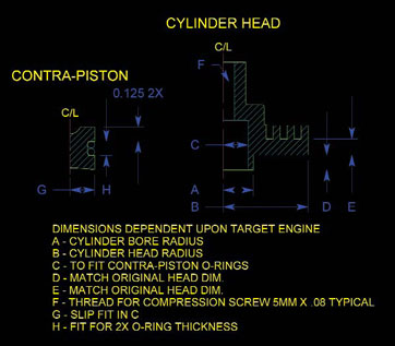
Most modellers have heard of or seen magazine ads for diesel conversion heads for our two-stroke glow engines. Although running model diesel engines hasnt been extremely popular in North America, model diesel aircraft engines have been commonplace in the rest of the world, including Great Britain, Australia, New Zealand and many European countries. Many model engine companies do not produce dedicated diesel engines, so it is popular to buy a conversion head which replaces the fixed compression glow head. These conversion heads have adjustable contra-pistons, a unique movable plug which sits within the head and can be adjusted up and down to vary the volume of the cylinder, and therefore the compression ratio.
Commercial heads are not always available for each brand and size of engine, but that can be easily overcome. If you want to try crafting a head of your own, all you need is a little aluminum and a lathe and drill press. Nearly every club has someone with, access to, these basic machine tools. If you dont have the tools yourself, buy a box of donuts and see if your clubmate has some free time one evening or weekend afternoon. You dont need large equipment for this project either. Sherlines lathe and mill, or even a benchtop drill press, are more than capable of producing a model diesel head.
This brief article explains how I produced a diesel head for a small two-stroke engine. This design was refined over many prototypes and many hours of running. I have made several hundred heads for other modellers and all have been successful with positive feedback.
A MODEL DIESEL PRIMER
Model diesel engines are really compression ignition engines. The heat caused by compressing the fuel-air mixture actually initiates ignition. Typical model diesel fuel is a mixture of kerosene, lubricating oil, and ether. A small percentage of an ignition aid is also commonly used, typically two to three percent by volume of either amyl nitrate or iso-propyl nitrate. A common mix for modern ball bearing equipped, ABC type engines would be 45 percent kerosene, 30 percent ether, 22 percent oil and three percent amyl nitrate. For older lapped iron/steel engines with plain bushings, you can lower the kerosene slightly and increase the oil content. For smaller displacement engines, reducing the kerosene and increasing the ether will make starting and tuning easier. Mixing your own fuel is not difficult, but obtaining the raw materials is not easy in all areas. It is often best to buy a premixed fuel if at all possible. Fuel can be purchased from Eric Clutton, a.k.a. Dr. Diesel, and Bob Davis of Davis Diesel Development.
Tuning a diesel is not harder than tuning glow engines. However, it is different. To start, you back off the compression adjustment screw, and with the needle valve set slightly rich you prime the engine and start flipping (a starter is generally not a good idea due to the higher compression and chance of hydraulic lock and damage to the connecting rod and/or piston) while slowly increasing the compression setting. The engine will start to fire, and once it starts running you increase compression to smooth out the firing cycle, and at the same time lean out the mixture until the engine is running cleanly. It is a balance of the needle valve and compression setting which seems difficult at first. However, in practice it is quite easy! It is one of those things that is easier to demonstrate, than try and explain how to do it.
Why one would want to run an engine as a diesel- is a topic debated by many modellers. Due both to the properties of kerosene and the fact the compression and therefore ignition timing can be adjusted, model diesel engines can turn larger propellers without overheating, they run longer on the same volume of fuel, and of course can be started and run without any batteries, and there is no glow plug to burn out. They are just another alternative to running engines with glow fuel or gasoline. You will find that the neat factor is quite high and a diesel certainly smells and sounds different!
BUILDING YOUR OWN DIESEL CONVERSION HEAD
Lets go through the process of producing your own home made conversion head. If anyone has any questions, you can email me at andrewc @flyrc.com and I will try to help.
| 1 | The first step is to remove the head from the glow engine and measure the outer diameter. I use 6061-T6 aluminum round stock to produce my heads. It is cheap and easily obtainable. It also machines well and is more than strong enough to withstand years of use. Cut off a one inch long length of the nearest size to the head you wish to make. In this case, I am making a head for an MVVS .12 and selected some 1 1/2-inch aluminum stock as it was the closest I had in size. | 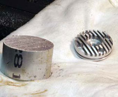 |
| 2 | Next, measure the portion of the head which sits within the bore of the cylinder. I select O-rings which are just slightly smaller than the cylinder bore. In my case, the cylinder bore was 0.530 inches, and I used 7/16-inch outside diameter O-rings. If you can get Viton rubber O-rings, they will last a much longer time than regular rubber rings. | 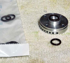 |
| 3 | Chuck the aluminum blank into your lathes three-jaw (self centering) chuck. Leave approximately half sticking out past the jaws. Face off the front of the blank and then, after measuring the bore and depth of the heads lower section (the portion which sits within the cylinder), turn the blank replicating the stock dimensions. In my case, the bore and depth are 0.530 and 0.130 respectively. Use a sharp cornered turning tool to get the inside corner sharp and without a radius, so the new head will sit tightly onto the top of the cylinder liner. | 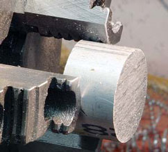 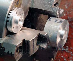 |
| 4 | Now, using center drill, drill the blank and follow up by drilling a pilot hole for which ever size tap you are going to use (matching the thread size of your contra piston adjustment screw). I use a 5×0.8mm machine screw for my adjustment, and use a no. 19 drill bit to pilot. Follow that up by tapping the hole all the way through. | 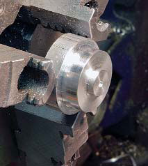
|
| 5 | The last step before removing the head blank from the lathe chuck is to bore the cavity for the contra-piston. In my case, with the size of O-ring I use (7/16 OD, 1/16 cross sectional thickness) I am making the bore a depth of 0.4375 inches. I always use two O-rings side by side in my heads (and recommend you do as well). I like to leave close to 1/8-inch on the lower section of the contra piston, and nearly that much on the top (for strength). I know my contra will be close to 3/8-inch total height, so my bore will be 7/16-inches deep. From my experience, in an engine of this size, the 1/16-inch left for varying the height of the contra-piston will provide enough compression adjustment. In a larger engine, or one using a smaller diameter contra-to-cylinder bore ratio, you might want to leave a little more adjustment height. Use a small boring bar and make a smooth, clean bore. It is essential to get the inside diameter smooth to avoid wear on the O-rings. | 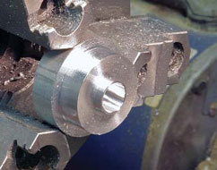 |
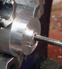
| 6 | Now, remove the head blank and turn it around. It is time to turn the opposite end of the blank in order to shape it and remove weight. I generally leave the main part of the head similar in size to the original head, with a portion above it turned to accept the inner bore, and a third section higher still turned down just to provide enough threads for the contra adjustment screw. You will have to adapt your design to work with your own dimensions of contra-piston bore and diameter. | 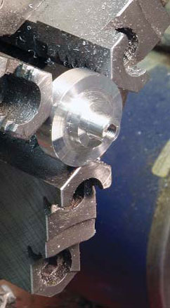 |
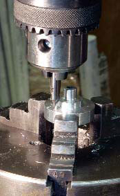
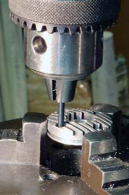
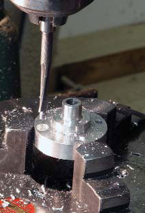
| 7 | To drill the head to match the original holes for mounting, I place the original head into a three-jaw chuck mounted on a rotary table mounted on a mill-drill machine. Selecting a drill bit that matches the original, move the X-Y table to line up the drill shank with one of the holes in the head. Then, remove the original head and place your blank into the chuck. Starting with a center drill, drill the required number of holes, in this case, four spaced 90 degrees apart. With the rotary table it is easy to get all holes properly located. Remove the center drill and use the drill bit to drill through the head again in all positions. The last step is to counter bore to provide clearance for the socket head cap screws which hold the head onto the cylinder. Measure the original for the proper depth and make your diesel head the same. Doing so will allow the same screws to be used for mounting.
|
|
| 8 | The next step is to machine cooling fins into the head blank if desired. It is not absolutely necessary, as most engines will run fine with a solid head and no cooling fins. However, they look nice and are not hard to machine. I use a smaller rotary table, with a chuck that has sacrificial aluminum jaws to hold the head blank. A 90-degree bracket holds the head sideways, and allows the 1/16-inch thick saw mounted on the mill head to cut by moving back and forth. Be careful not to cut into the heads cavity or threaded portion. Once the fins are cut, you can remove the completed head and clean it with detergent. Trial fit into the engine, and make sure it fits as snugly as the original head into the cylinder, and that the piston does not contact the head at TDC. Check the head bolts for accuracy and proper depth. | 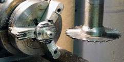 |
| 9 | The next step is to machine the contra piston itself. Turn a piece of 6061-T6 aluminum to the proper diameter (I try and get the contra piston half of a thousandth smaller than the bore, this allows the contra to be snug yet move easily with the adjustment screw and prevents the aluminum from galling which can happen if you try for too tight a fit). Turn the visible end, which will be the bottom of the contra, with a shallow dish profile. A few degrees is enough. Then, using a small round end tool bit, machine the groove for the two O-rings. I cut the groove the exact depth and twice the width of the O-rings cross section. Chamfer the edges and part off the contra-piston. | 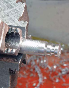 |
| 10 | The last step in machining the contra-piston is to chuck it into the lathe and using a ball end mill, make a small cavity in the upper end. I hand file the end of the contra-piston adjustment screw with it in the lathe to match. This gives a smooth adjusting contra-piston and prevents wear of the relatively soft contra-piston from the hardened machine screw. After cleaning the contra, slip the two O-rings into the groove and trial fit into the head cavity. It should be a snug fit without damaging the O-rings. This allows easy replacement of the O-rings, yet a long term, leak free seal. If your O-rings are very tight, a little silicone grease will ease getting them into the head cavity. | 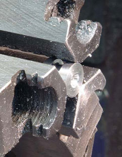 |
| 11 | The final step is to provide a means to lock the adjustment screw. In some cases, I drill the threaded portion to allow a 3mm set screw to lock the adjustment screw. Sometimes, a Tommy bar is used to allow easy adjustment without tools, and a locking nut is used to hold the bar from vibrating out of position. In this case I machined a small handle from brass stock and silver brazed it to the top of the machine screw after grinding off the black oxide coating. The last step is to make sure that with the adjustment screw screwed all the way down it cannot push the contra-piston past the edge of the head. This will prevent the contra from ever contacting the engines piston and causing a lot of damage. If the contra drops too low, either file the screw end shorter, or mill the dimple in the contra-piston deeper. | 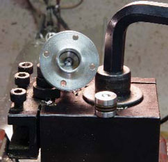 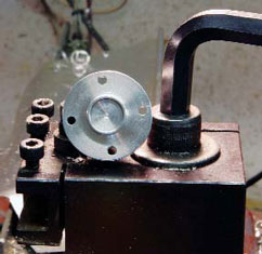 |
 CONCLUSION
If you like trying something different, try running one of your engines as a diesel. Making the head yourself is sure to impress some of your flying buddies and even your, and lets you run an engine for which a commercial diesel head may not be available. The machining steps are straightforward and not at all that difficult, making this project perfect for beginning machinists and experts alike. It is an enjoyable way to explore the hobby further!
Good luck and happy dieseling!
Links
Dr. Diesel www.cafes.net/doctordiesel
Davis Diesel Development www.davisdieseldevelopment.com (203) 877-1670
Sherline www.sherline.com (800) 541-0735
