 Fly RC Magazine WE LIVE RC
Easy Music-Wire Landing Gear
Spring steel wire, also known as music wire, is one of the most popular model landing-gear materials. It is readily available at most hobby shops, inexpensive, strong and easy to form into just about any shape imaginable with common tools. Whether you are scratch-building a new design, building a kit, or just repairing the gear for your latest ARF, no modelers skill set is complete without a few basic techniques for working with music wire.
DESIGN CONSIDERATIONS
A recent scratch-building project gave me a perfect opportunity to exploit the advantages of music-wire landing gear over aluminum and composite construction. Because the landing-gear legs for this design sweep forward, modifying an existing aluminum landing-gear blank would have meant dealing with concave angles on the front side where the gear legs meet the center section. This would have meant a lot of filing to produce a cleanly finished part. I also didnt want to create a form to mold composite gear, so music wire got the nod.
My landing gear has a main leg thats bent out of 1/8-inch wire and incorporates the axles. A second supporting leg is made of 3/32 music wire. I bound and soldered these two pieces together near the axle. This created a triangular structure that resists any rearward motion of the gear leg but still allows it to flex outwards and absorb landing stresses.
TOOLS
You will need a few basic tools for measuring, cutting and bending music wire. I use steel rulers, a Dremel tool with a fiberglass-reinforced abrasive wheel and the Stevens AeroModel wire shears. Stevens also sells K&S wire benders, as do several other vendors. For measuring and alignment, I use a sliding bevel to check angles, and I use a speed square for referencing the grid on the Great Planes Magic Magnet Building Board when I line everything up.
Last, dont forget to wear your safety glasses whenever you work with grinding or cutting tools and hot solder.
BENDING THE WIRE
The first step is to determine the bends youll need to make to achieve the final shape you need for each of the components. A published plan or kit instructions usually give the correct gear geometry. If you dont have a drawing or a sample to copy, I recommend that you use soft wire like clothes-hanger wire to determine the shape before you move on to bending the harder music wire.
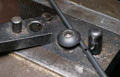
Getting the bends exactly where you want them can be a little tricky. I lay out the bends following measurements taken from the fuselage centerline, and I mark the wire using a permanent marker. You could clamp the wire in a vise and hit it with a hammer, but a little more finesse is worth the effort. Years ago, I bought the K&S Metals Mini Wire Bender, and it has always given me dependable service. It clamps the wire against a fixed pin and features a pivoting handle to give you the mechanical advantage you need to bend the wire.
   |
SOLDERING
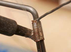
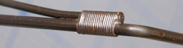
If you have more than one piece of wire for the landing gear, you need to join the individual pieces. Binding the joint with copper wire and soldering is the traditional way to go, and most designers recommend the use of a very strong silver solder such as Sta-Brite. If you do not have silver solder, dont despair. Ive successfully used traditional 60-40 solder for smaller models.
For satisfactory results, before you apply heat, your parts must be free of rust and other contaminants. First I wipe the wire with denatured alcohol on a paper towel to remove surface oils; then I then scuff it with a Scotch- Brite pad or fine sandpaper. I find it easiest to do a major cleaning before I bend the wire, and then, to remove any contamination that may have occurred during the forming process, I give it a final wipe-down right before I bind and solder. The last step is to apply flux to the joint to clean it chemically. The Sta-Brite flux is a liquid; carefully put a couple of drops on the joint to ensure it goes where you want it.
  |
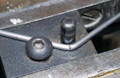
In addition to cleaning, the correct application of heat is critical. I use a Weller WTCPT soldering station with an 800-degree, 1/4-inch chisel tip, and I apply ample heat to the side thats opposite the part where I introduce the solder. Let the solder flow through the wire binding, and then remove the heat and let the solder cool before you move it. It is imperative that the structure be rigidly held while the solder cools. If you bump it, you will probably have to apply a little more flux and reheat it so that it cools with a smooth, shiny surfacea sure sign of a good soldering job.
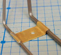
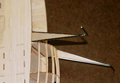
After soldering the joint near the axle, I bent and soldered 0.020-inch brass sheet mounting pads between the wire legs. Your model may allow you to use nylon mounting clips. Now clean off any residual flux with a wire brush.
  |
FINISHING
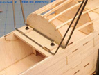
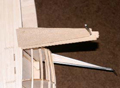
With the bending and soldering done, instead of leaving the wire gear bare, consider some sort of finish. You could paint the wire to match your model with a high-quality primer and spray paint. For this project, I added a balsa fairing because I planned to cover it with iron-on film.
I used three layers of 1/8 balsa to create the fairing, carefully fitting the central core to fill the area between the two wires. Additional strips outside the wires fill the gaps between the two outer layers. I assembled the balsa with Mercury Adhesives medium CA and then sanded it to shape. After a bit of sanding, the landing gear is ready to cover.
  |
CONCLUSION
As you can see, there arent any real secrets to soldering music-wire landing gear. Simply bend the parts accurately, and clean them well before you apply enough heat and the appropriate solder. With only a little practice, you will soon be able to make gear that is strong enough to prevent your model from making unintended belly landings and looks great to boot.
Links
K&S Engineering, www.ksmetals.com (773) 586-8503
Mercury Adhesives, www.mercuryadhesives.com (770) 886-9566
Stevens AeroModel, www.stevensaero.com (719) 393-0830
