 Fly RC Magazine WE LIVE RC
 Frank Tiano |
 Simpler to install than you may think, and rewarding
At one time, there were perhaps a half dozen or more procedures associated with building model aircraft that were considered difficult, unusual and sometimes downright intimidating. These included applying fiberglass cloth and resin to a wood structure, sheeting foam wing cores, building washout into wing panels, applying heatshrink covering material, and installing a set of retractable landing gear. Since we are knee-deep into the wonderful world of ARFs, most of those mysterious procedures will never have to be explained again. All except one, that is. And that one is the dreaded Retract Gear Installation,or RGI, as we like to call it.
On any given Sunday, you can visit any of a number of local flying fields and find the club members hanging out and kibitzing about anything from something that happened 27 years ago to what engine Joe ought to be using in that Ugly Stick instead of the one that keeps quitting every time he throttles up! Sooner or later, one of the regulars will mention that he is thinking about buying one of those new war birds, one that has retracts and flaps. Well, just the mention of the Rword (retracts) is going to get him about six different opinions as to why he is a lunatic for considering such an unreliable option!
In a nutshell, hell be told that retractable landing gear is difficult to install, unreliable in its operation, and prone to failure—perhaps as much as 75 percent of the time. Well, Im here to tell you that the aforementioned statements about retract gear are absolute hogwash, balderdash and nonsense! Modern retractable landing gear is about as reliable as any quality radio, assuming that you follow the directions for installation and operation. In fact, if any RG system ever does fail, it is most likely the fault of the installation or the lack of maintenance! The balance of this article will deal with the most popular types of retract gear available and the installation of one of the more popular systems in use today.
RETRACT BASICS
The retract gear units themselves, not the parts that make them work, are usually fashioned from metal. There are some really lightweight versions made from plastic, but these are for very small models. The retract units have a sliding bar connected to an air cylinder or to a pushrod connected to a servo. The sliding bar slides within the retract gear chassis, pulling or pushing another part, the trunion block,as it goes back and forth. The trunion has a machined hole in it, and thats where the landing gear strut is installed. Because the trunion is captured within the retract gears chassis, as the trunion is pulled and pushed, it pivots. Since the landing gear strut is plugged into the trunion, the strut retracts and extends.
 MECHANICAL
Whether the retract unit is controlled by a servo or an air cylinder is incidental. However, you will find that servo activation is typically used in smaller models incorporating smaller retract units. Once we get to the point where we are trying to retract a gear strut measuring over 1/2 inch in diameter with a five-inch tire on its axle, we find that only the air-operated gear will function properly. Servo-operated gear installation
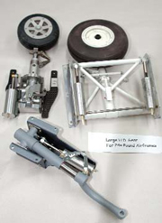
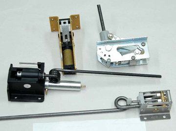
These are heavy-duty gear intended for rather large models. The light gray one is a Robart unit for the Ziroli T-6, the wide gear with the white wheel is a Robart main gear for the Frankel T-34, and the exquisitely machined gear in the upper left is a BVM nose gear for their large F-86 Sabre Jet.
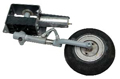
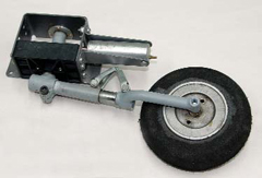 This style gear, from Robart Mfg., might be considered for medium sized models. It is specifically designed for the Midwest T-6, an 80-inch, 18-pound airplane. Notice that the strut is actuated from the front of the gear unit, thus placing the strut and tire in the scale location when retracted.
procedures are really quite simple. You merely install the servo, usually one of the retract variety which has 180 degrees of rotation, and run a pushrod from it to the landing gear chassis. The landing gear unit is manufactured with a locking system so that the servo isnt taking side loads during landings. The air-operated type of retract is far more popular and just a bit more intricate, but simple just the same.
 PNEUMATIC
Air-operated units have an air cylinder attached to their chassis. The air cylinder has a metal nipple at each end. The air cylinder houses a metal rod, usually about 1/8 to 5/32 inches in diameter, that runs down its center. As air is pumped into one end of the cylinder, the rod extends, pushes
Small gear handle the average 60-inch model really well, and they sometimes work well with larger models. Starting with the black gear and going clockwise, we have a typical Chinese manufactured nose gear that comes as standard equipment with many ARF models. Spring Air manufactures the gold-colored main gear. Next, the shiny aluminum gear is a rotating unit by Robart that fits many 60-inch models like the Corsair and P-40. In the lower right, we have the FTE mechanical gear for airframes exceeding 10 pounds (all the way up to 15, in fact). These are a popular replacement for standard, servo-operated ARF gear.
against that trunion block holding the strut, and the gear retracts. Then, as the air is pumped into the other end, it reverses its operation and causes the strut to extend. Its operation is really quite simple.
 If care is taken to properly fasten the miniature air line tubing to the air cylinders, the Tfittings, and other components, the system should operate without failure for a very long time. You may develop a leak in the tubing if something is rubbing against it and eventually chafes through it and causes a crack or tear. You could also develop a leak if an air line lets loose from its nipple.
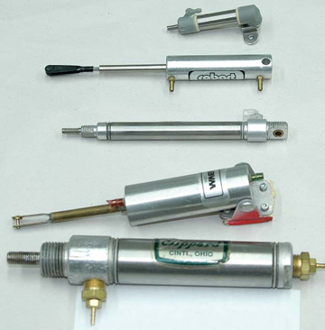
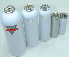
An assortment of air cylinders that can be used to operate retract units or to close landing gear doors. The BVM manufactured cylinder at top is available in several sizes, as are the Robart styles, placed just beneath it and second from the bottom. The slim cylinder and the one at the bottom are from Clippard Mfg., a company that specializes in all types and styles of air cylinders. The larger the diameter of the cylinder, the more powerful it is.
We normally replace the air lines every five years or so. Air-operated retracts need a few parts to support their operation. A filler valve is used to get air into a storage tank, and an air valve controls the retraction by directing air pressure from the storage tank to the air cylinders. A small servo actuates the air valve, sending its internal plunger back and forth, diverting air to one end of the retract air cylinder or the other.
 ROBART MANUFACTURING
The company known worldwide for the widest selection of retract gear packages is Robart Manufacturing, out of St. Charles, Illinois. Robart makes all sizes and all styles of retractable gear—from little tiny units suitable for 1/2A models all the way up to huge units that will handle the large struts and heavy tires commonly found on a model weighing in excess of 50 pounds!
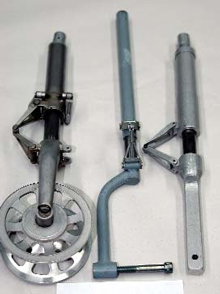
There are literally hundreds of designs of landing gear struts available, and here is a small selection of some that are commonly used on 80- inch warbirds. From left to right, we have a super scale set for a Dave Platt or Top Flite Mustang, followed by a generic large Robart Robo Strutand then a Gene Barton strut made specifically for 92-inch P-47b Thunderbolts. Notice that all have working scissors to dampen the shock during landing.
EXAMPLE INSTALLATION
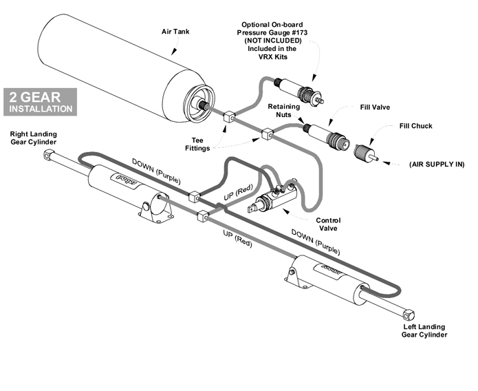
Lets run through a simple gear installation in something common, something with just main gear retracts, like a Ziroli T-6 or a sport scale ARF such as Top Flites P-51 or Hangar 9s P-47. Im sure you can relate to one of those models. I like to keep things neat, so the first thing I do is get all the components together on the bench and in front of me. That would include the gear units and their directions, the struts, axles, wheels and tires, air filler valve, air storage tank, air actuator valve, several Tfittings, and two pieces of air tubing in two different colors and each about three feet in length. I like to color code the upand downlines so that I can easily troubleshoot them if needed.
The next thing is to fasten the air line tubing to each nipple on the retract unit, leaving about two or three feet dangling so that there is plenty of tubing to reach from the retract gear unit to the air valve. Depending on the installation, you may need to incorporate the use of some quick disconnectsbetween the wing and fuselage. You plug these airtight fittings together, just as you might plug your aileron servo lead into the pigtail coming out of the receiver before you fasten the wing to the fuselage.
Then, I install the gear units and route the air lines toward the center of the wing. If there is sufficient room (the lines are not interfering with servos or linkages), I would mount the retract valve right onto the top surface of the wing center section. Otherwise, mount it to the fuselage side. A small servo can then be mounted, in line with the air valve, so that it can actuate the valve via a short pushrod.
The air lines from the front of each retract unit are fastened to the front pair of nipples of the air valve while the rear pair of air lines (a different color than the front) are fastened to the rear pair of nipples of the air valve. The air filler valve is installed where it is convenient to get to but not obnoxious to look at. The air storage tank can be attached with a Velcro hook and loop fastener to the inside of the bottom or on one side of the fuselage. Next, I run one small piece of air tubing from the fill valve to one side of the T fitting, and another from the air storage tank to the other side of that T fitting. Finally, from the last nipple of the T fitting, I would run a piece of air line to the last open nipple port on the air actuation valve.
The retract system is now installed. We can buy an inexpensive 12-volt tire pump at any hardware store and use it to pump our system full of air. The better air pumps have a pressure gauge on them, and we look for 100 pounds of air pressure to be pumped into the air storage tank. We must make sure that the pressure gauge shows a steady 100 pounds of pressure; allowing it to reach 100 and turning it off will actually result in less than 100 pounds of air in the tank. Hopefully, you will not hear any hissing sounds or see leaking air, as these are dead giveaways for a faulty air tubing connection. Silence really is golden!
Assuming everything is cool, you can operate the air control valve by hand and watch the gear retract and extend. If they slam open and shut, you might want to invest in a pair of Robarts inline air restrictors, which will slow the retraction speed considerably. If we introduced a retractable tail wheel or nose gear into the mix, all we would have to do is to Tinto either of the main gear UP and DOWN air lines and air would automatically be diverted to the additional gear as well.
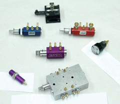 The best way to get air into a retract system is to pump it into an air storage tank via a fill valve.Once the system has air, the actuator valve directs air to either end of the retract cylinder as a servo pushes or pulls its centerline plunger fore and aft. Some valves, like the large silver one at the bottom, offered by Ultra Precision in Canada, will not only retract the gear but will time the closing of the gear doors. The standard, black valve at the top is from B&D; below it are two offerings from Robart: a standard blue one and a red one that allows control of the retract speed. The purple one in the middle is a BVM High Performance valve, which features more volume of airflow to help lift large, heavy struts and wheels.
Air tanks are a necessity to any retract gear system. The tiny tanks on the right will be fine for .40 to .60-size sport models. For really large scale models, ones with heavy gear and large air cylinders, the ones to the left are required. Two or three smaller air tanks can be placed in series to offer more air storage if larger ones are unavailable.
TIPS FOR SUCCESS
There are some common procedures that experienced modelers use to insure against air leaks. One is to make sure that all air lines are pushed completely onto their corresponding barbed nipples. Then, one drop of thin Zap should be placed at the joint to prevent the tubing from sliding off. Next, be absolutely certain that there are no kinks in any air line, anywhere. Kinked airlines can cause air lines to disengage from their nipples or cause one gear to work slower than the other, or perhaps not at all! Kinks can also interfere with the pressurization of the onboard air storage tank. Last, keep all retract gear free from dirt and grime. After flying from excessively sandy fields or after a crash, spraying the metal units with carburetor cleaner is a good practice. And following up with a light spray of WD-40 keeps them working smoothly and smelling terrific as well!
GEAR MANUFACTURERS
There are many gear manufacturers worldwide. Many more, in fact, than I know about or can recall. However, few are a full time business. Some kit manufacturers make excellent retract gear, but unfortunately, most of the time, these gear are designed specifically for one model only and are difficult or impossible to adapt to another.
Arguably, some of the finest jet gear in the world comes out of the BVM factory in Winter Springs, Florida. These gear seldom fail and always work smoothly unless theyre crashed. But as beautiful, robust and scale as they are, the F-86 gear will do you little good in a Top Flite Corsair, and so on. In some cases, one manufacturers gear will work on another manufacturers kit. For example, Dave Platts retracts can be fiddled with to make them fit many WWII aircraft. Separate struts must be fabricated, but the gear will work just fine.
Yellow Aircrafts landing gear for their Zero will fit Platts Zero as well. However, the only large gear company that makes both generic gear as well as gear for a specific scale subject is Robart. They make an entire line of gear, air-operated and servo-activated, that fit a large variety of scale and sport aircraft. A visit to their web site is a must: www.Robart.com. Much like BVM, Robart offers various scale or scale-looking struts in various sizes, as well as wheels, tires and brakes to complement their gear packages. Like Robart, BVM offers upscale air control valves, filler valves and several other retract accessories or components that will work perfectly on any sport or scale model. That information can be found at www.BVMJets.com.
When it comes to large-scale models, say 80-inch wingspan and above, Robart is about the only way to go for a commercial set of gear. By commercial, I mean gear that is in stock and available in a reasonable amount of time. If you need a custom set of gear, and dont mind waiting somewhere between two and 22 weeks, you can contact Sierra Precision Gear and Gene Barton Gear. However, be prepared to pay at least double the price, compared to a commercial set, for anything custom.
I hope this combo of text and photos has helped to clear up any of the mystery that may have been associated with retract gear installations. As you can see, the installation process is quite simple and is very rewarding when completed. I promise that if you decide to go that extra distance to install a set of retracts in your next model, you will become one of the thousands of happy modelers who just love saying those magical words: Gear UP and Locked!
Links
Bob Violett Models, www.bvmjets.com , (407) 327-6333
Robart Mfg., www.robart.com , (630) 584-7616
Sierra Giant Scale Gear, www.sierragiant.com , (440) 476-4885
