 Fly RC Magazine WE LIVE RC
By Jerry Mollica
 INTRO
INTRO
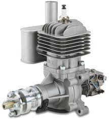
Perhaps the most ubiquitous gas-powered engine in the RC market, the DLE 30 has been around for a good while and remains a standard in the ¼-scale arena. Well known for reliable and consistent operation with a hefty dose of power to spare, the DLE 30 has found a home in all types of airframes from trainers to sport models and even multi-engine warbirds and civilian air buses. If treated properly, this engine can serve you well for hour upon hour of operation, but even the most conservative pilot will eventually need to crack that case open for a little maintenance or repair work. While this might be uncharted territory for some modelers, most gas-specific pilots are well versed in dis-assembling and re-assembling their power plants in record fast times. There’s no need to be intimidated if wrenching on one of these motors is in your future, but you have no clue where to start. Clear off that workbench and work alongside us as we guide you through the process.
First things first. We have to know exactly what we’re dealing with here. Yeah, it’s a DLE 30 Reed motor, but what does that mean concerning the inside of such a motor? Well, the Reed designation in the name tells us the first piece of vital information. There are two types of carb setups on these size motors. A traditional piston port carb is mounted up on the cylinder of the motor and is ported through to the piston… hence the name. Conversely, the Reed motors feature a crankcase mounted carb with a reed valve in the port. What this design does is increase the horsepower in addition to making the motor run more efficiently, but it also means there is more maintenance involved. The reeds tend to wear out after a while and will need replacing.
Aside from the difference in the carb mounting location, the DLE 30 is just like most other two-stroke gas engines in that they are fairly simple once you get down to it? a testament to their reliability. Starting from the outside, the breakdown goes like this. The crankcase is the housing for everything. Once inside, you’ll have full access to the crank shaft with a press fit pin that is mounted to the connecting rod. The rod is then secured to the top of the piston with a wrist pin and two spring clips. The piston is housed inside the cylinder or head, to which the exhaust is mounted. Still sound a little too complicated? Fear not. Grab your tools and let’s do this. The trick in working on one of these motors is a good set of tools, a nice clean work surface and a little elbow grease. Read through this article fully a time or two before diving in and don’t be afraid to ask questions online or at the field if you have any worries about the process.
TOOLS REQUIRED 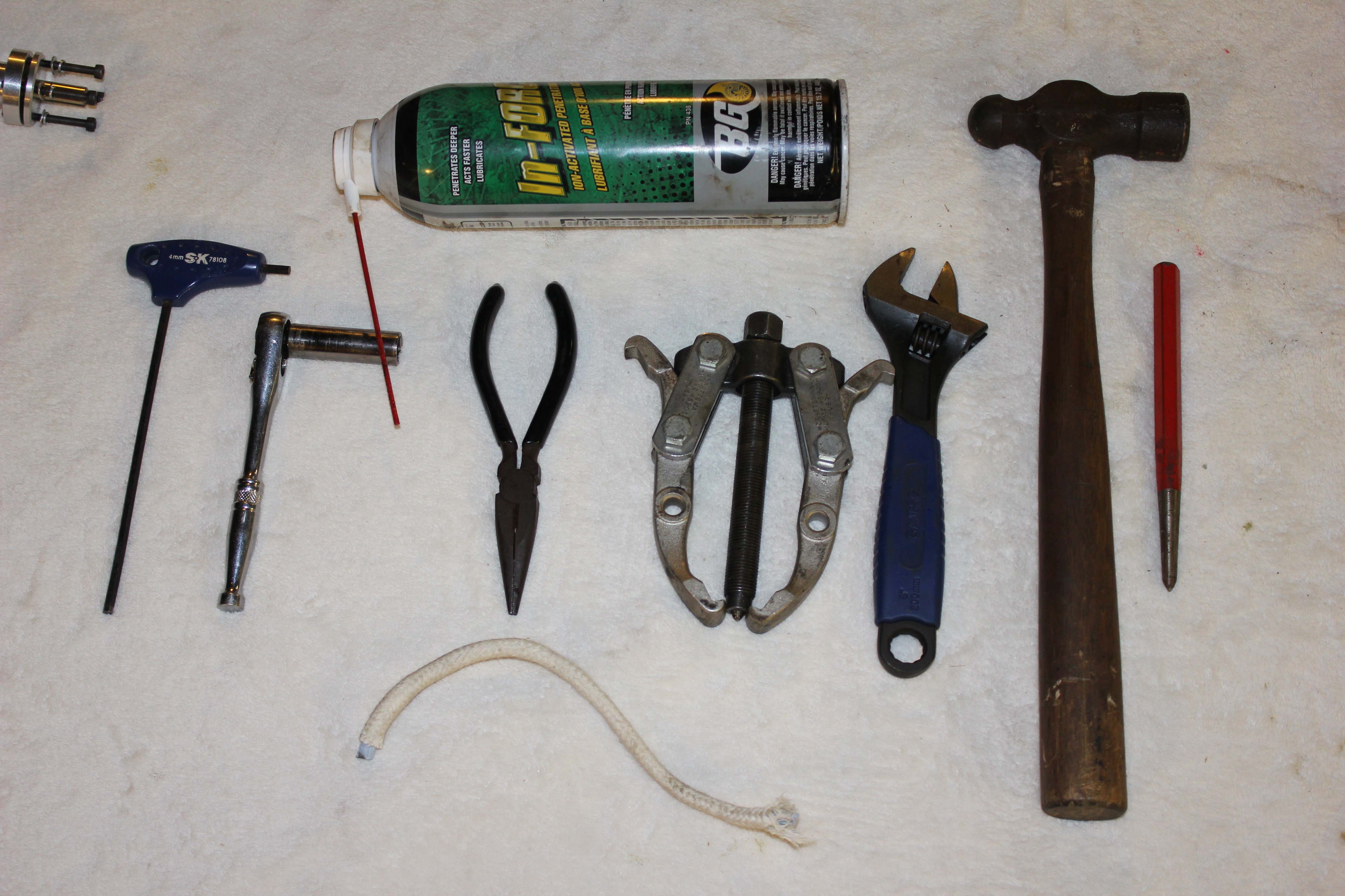
-4mm T-handle hex wrench
-11mm long-reach socket wrench
-Piston Locking tool or small piece of rope
-Gear puller and appropriate wrench
-Small wood handle hammer
-Beveled punch
-Needle nose pliers
-Light oil
-Blue thread lock
-High performance silicone
TEARING INTO IT:
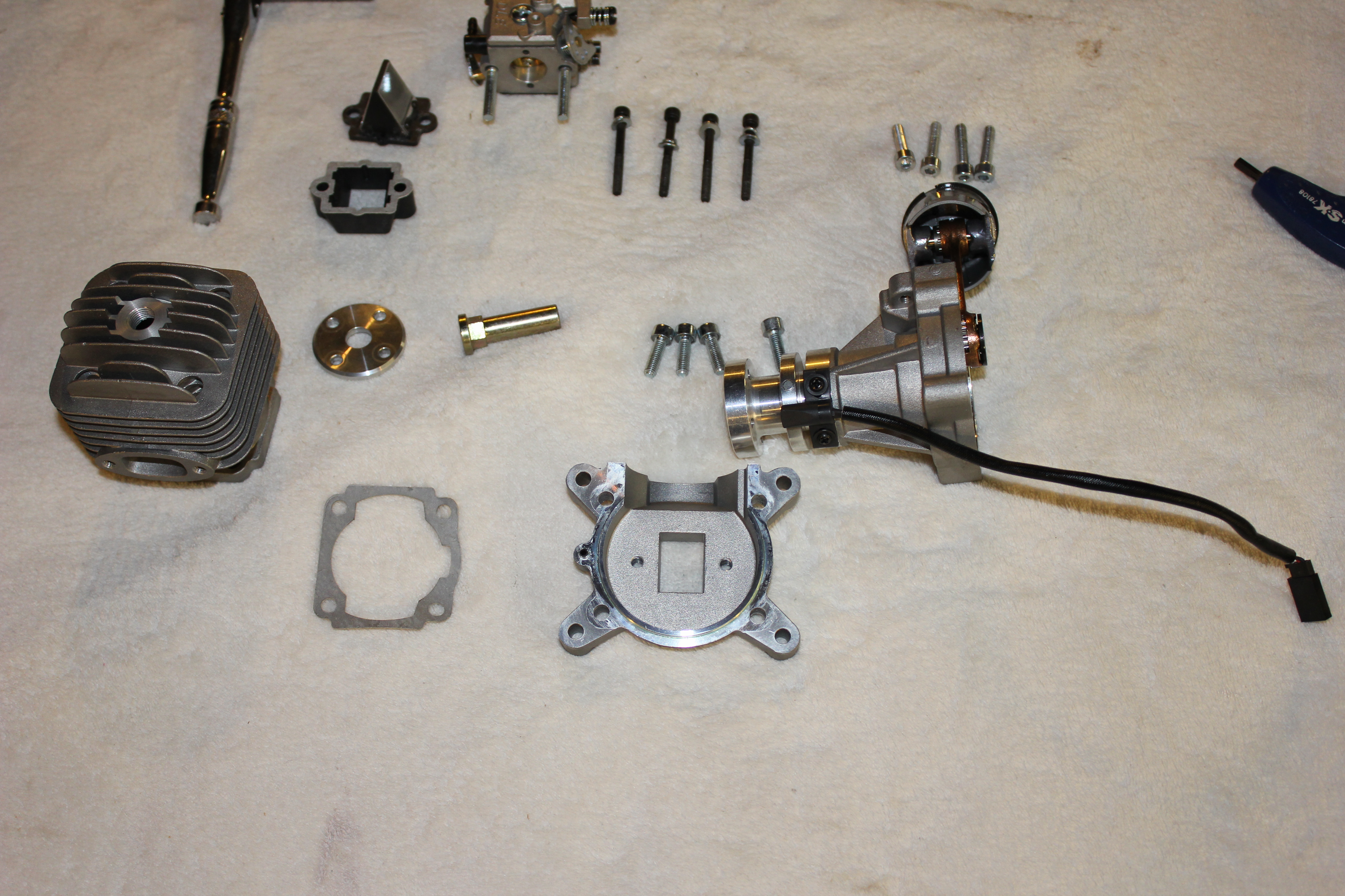
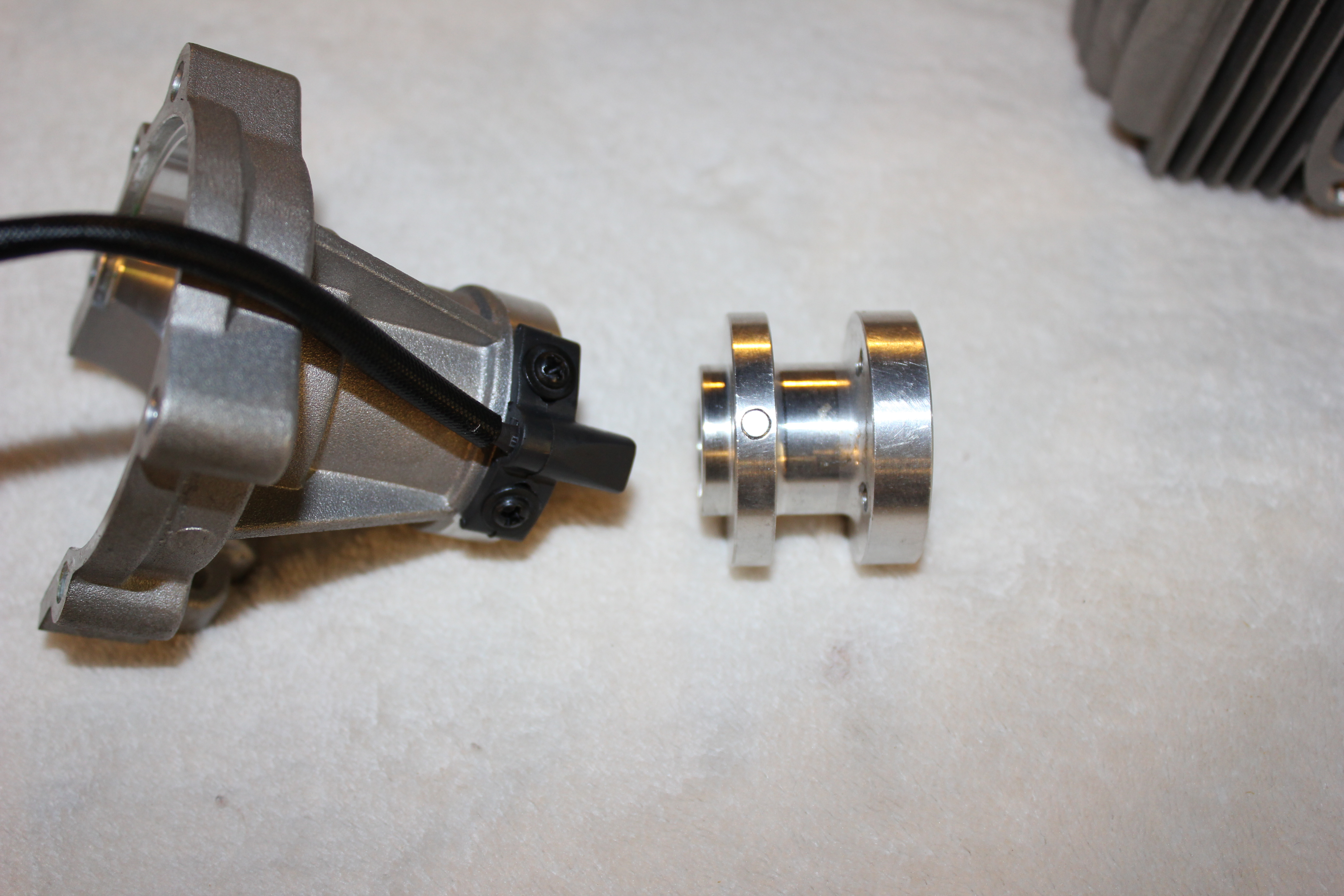
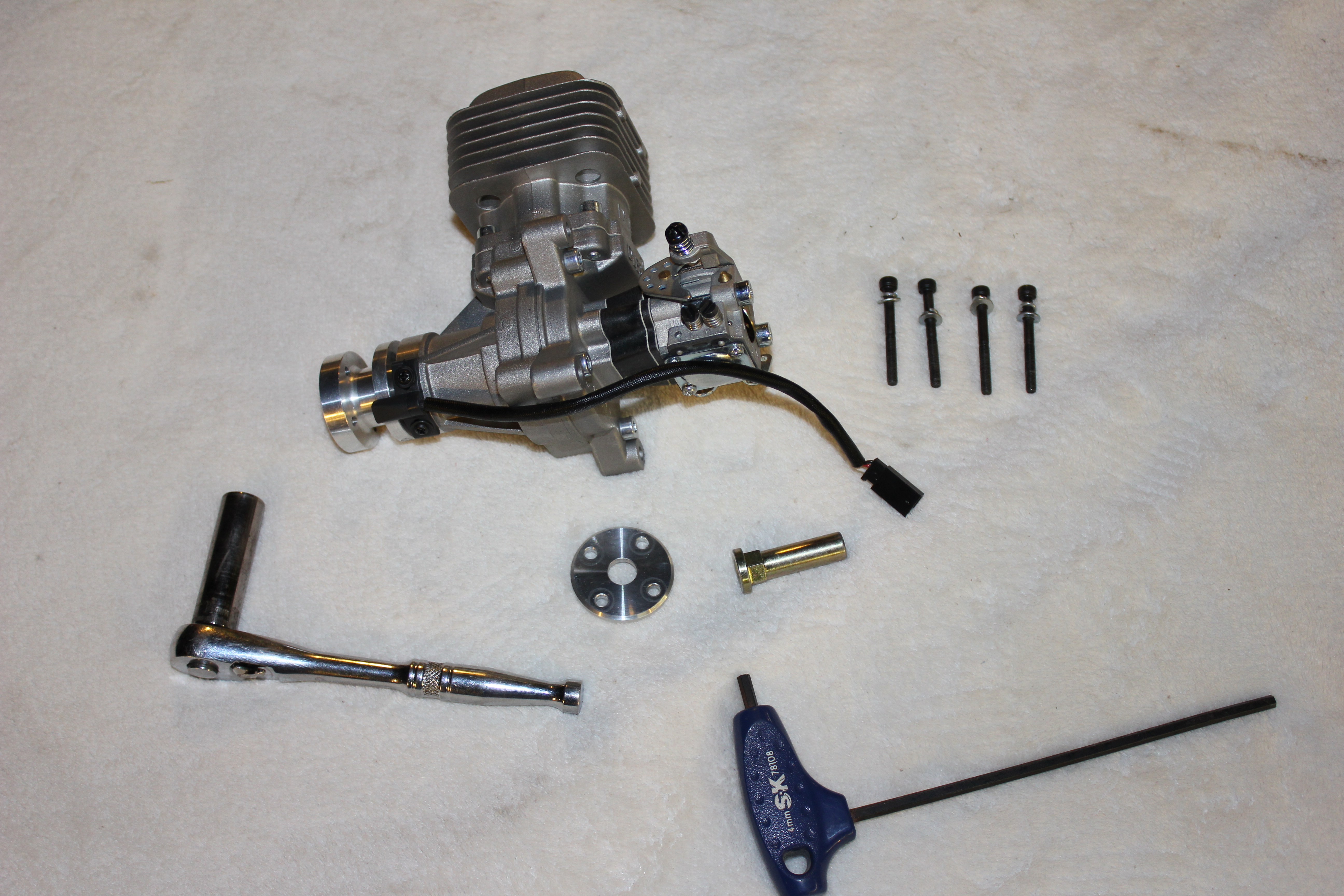 1) Remove the four-prop hub adapter screws with the 4mm hex wrench. Here’s where the T-handle comes in handy. Slide the adapter plate off and then unscrew the hub nut using the socket wrench. This is what we’re left with after those two steps. To get the hub nut off, lock the piston using a locking tool or a piece of clean rope.
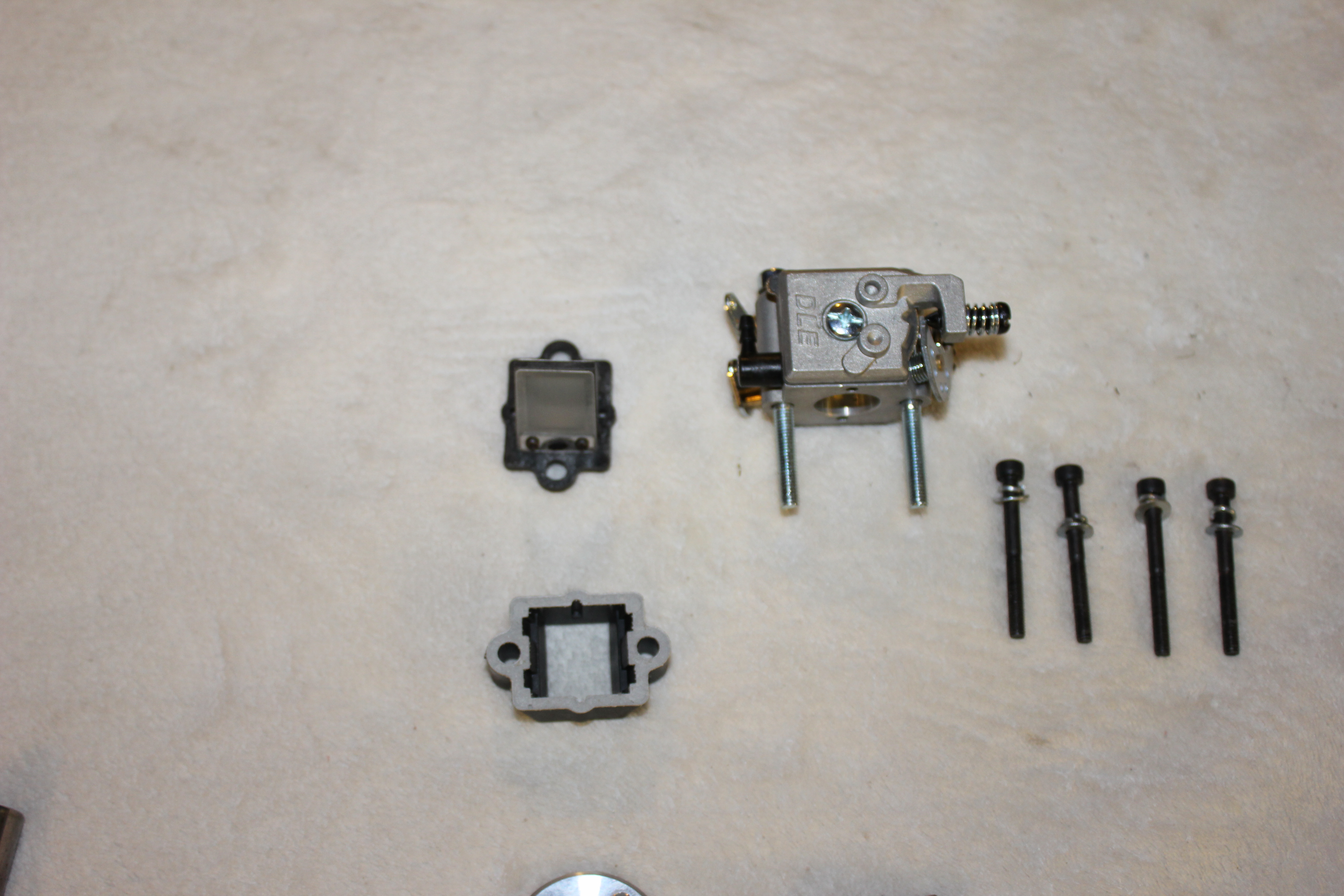
2) Next, remove the carb body by unscrewing the two screws with the 4mm hex wrench. Carefully pull the body, spacer and reed valve out of the crank case.
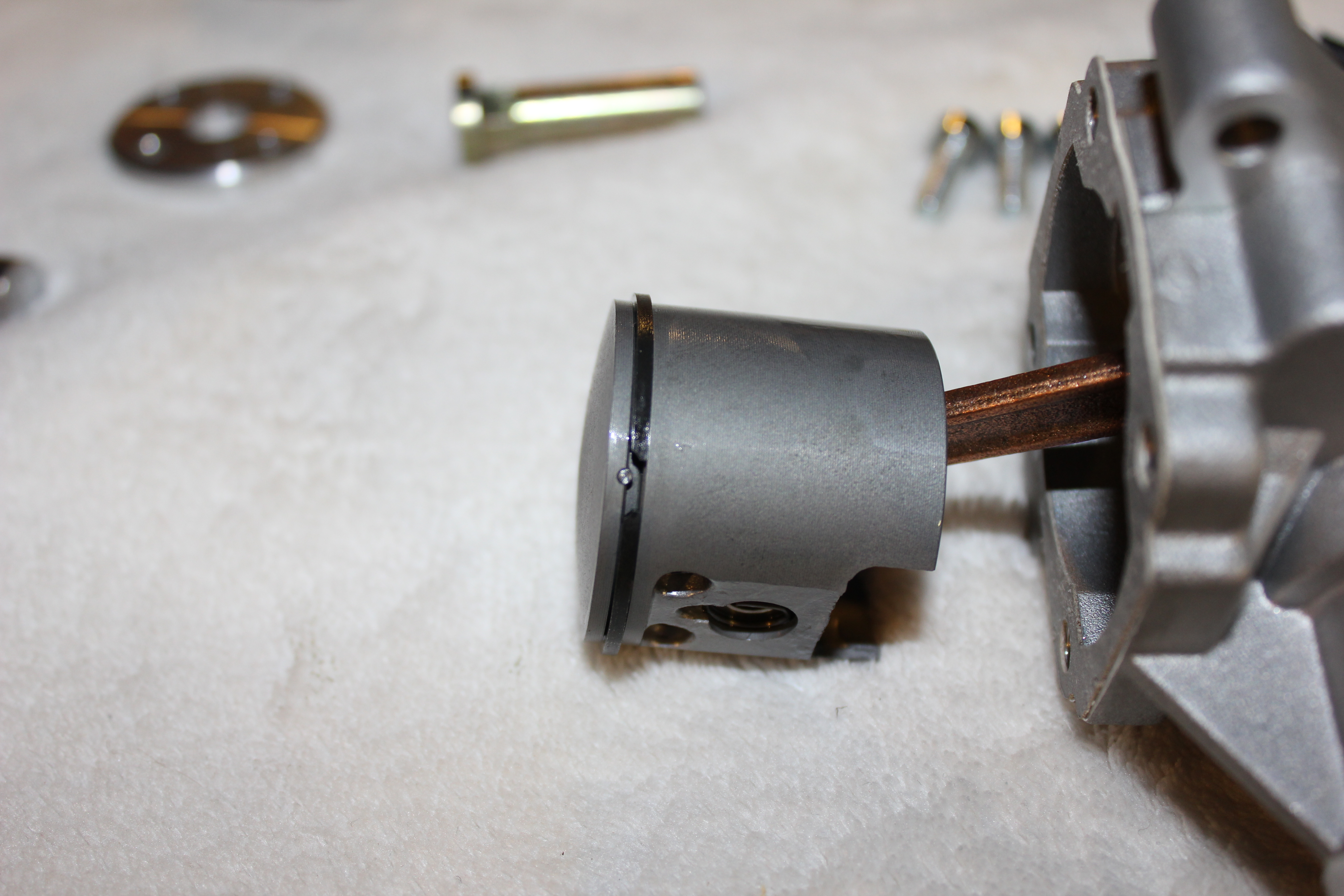 3) Now we can remove the four bolts holding the cylinder on the top with the hex wrench. Once the bolts are out, carefully, but deliberately slide the cylinder off of the piston. It might help to warm the entire motor up a bit with a heat gun, but don’t go too crazy as we still need to be able to grip it. Once the cylinder is off, this is what the piston looks like. Notice the pin in the ring groove. Be sure to note its location so it can be placed back in the same orientation for proper porting.
 4) Now that we’ve got the piston exposed, we can take the back plate off by removing the four screws with the hex wrench. The plate might require a little coercion to come off as they are sometimes coated with high performance silicone to create a good seal on the crankcase. Again, heating it up a bit might help. This is where we’re at once the back plate is removed.
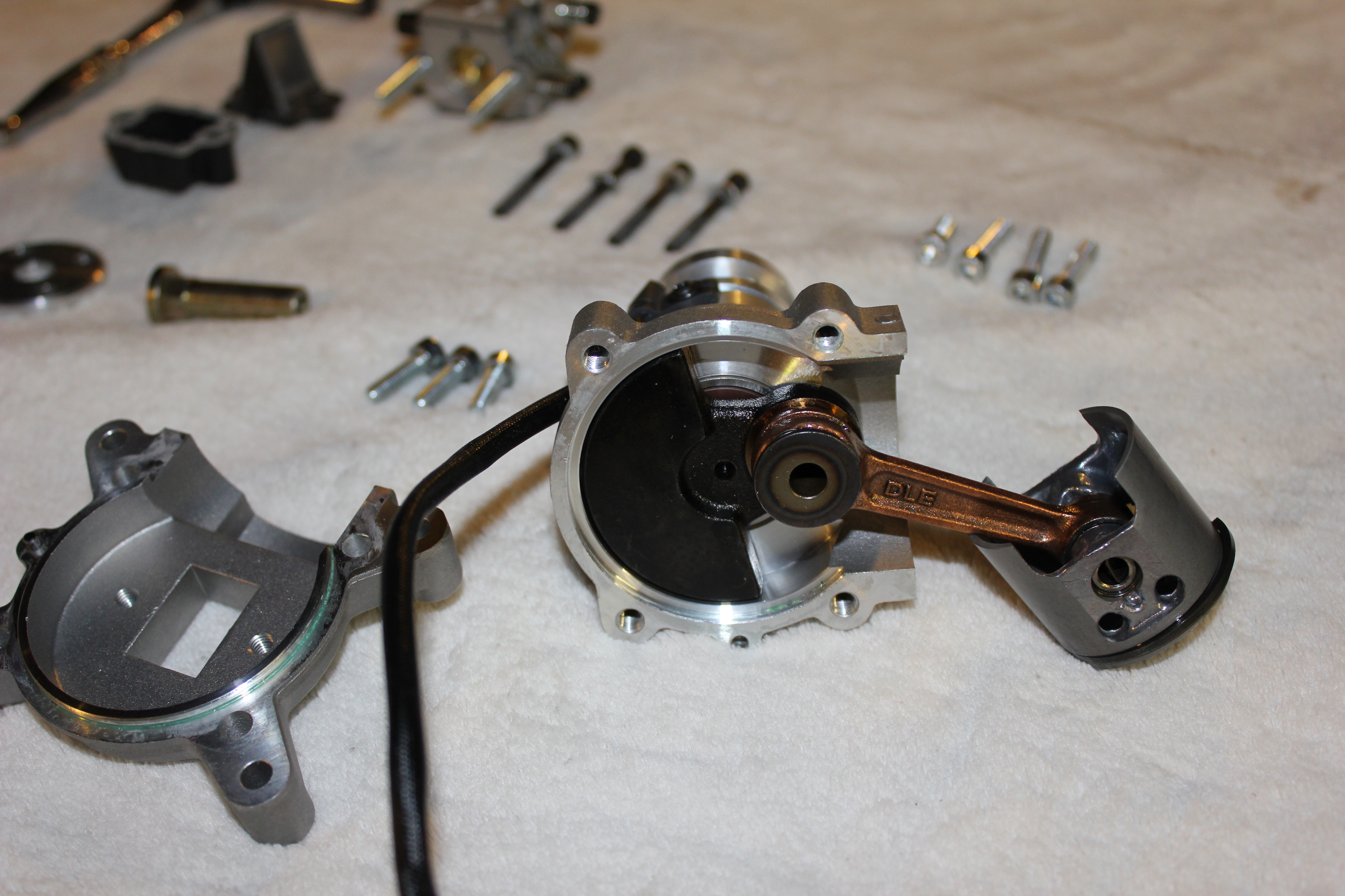 5) Here’s a look at the back of the crankshaft showing the pendulum and the press fit pin that secures the connecting rod to the crank. Though it is rare that the connecting rod needs to be replaced, if it does, you’ll have to source a crankshaft as the rod is factory installed on it.
6) After getting the back plate off, we move to the other side to pry the prop hub off the front of the crank using the puller. The inside of the crankshaft is beveled, just as your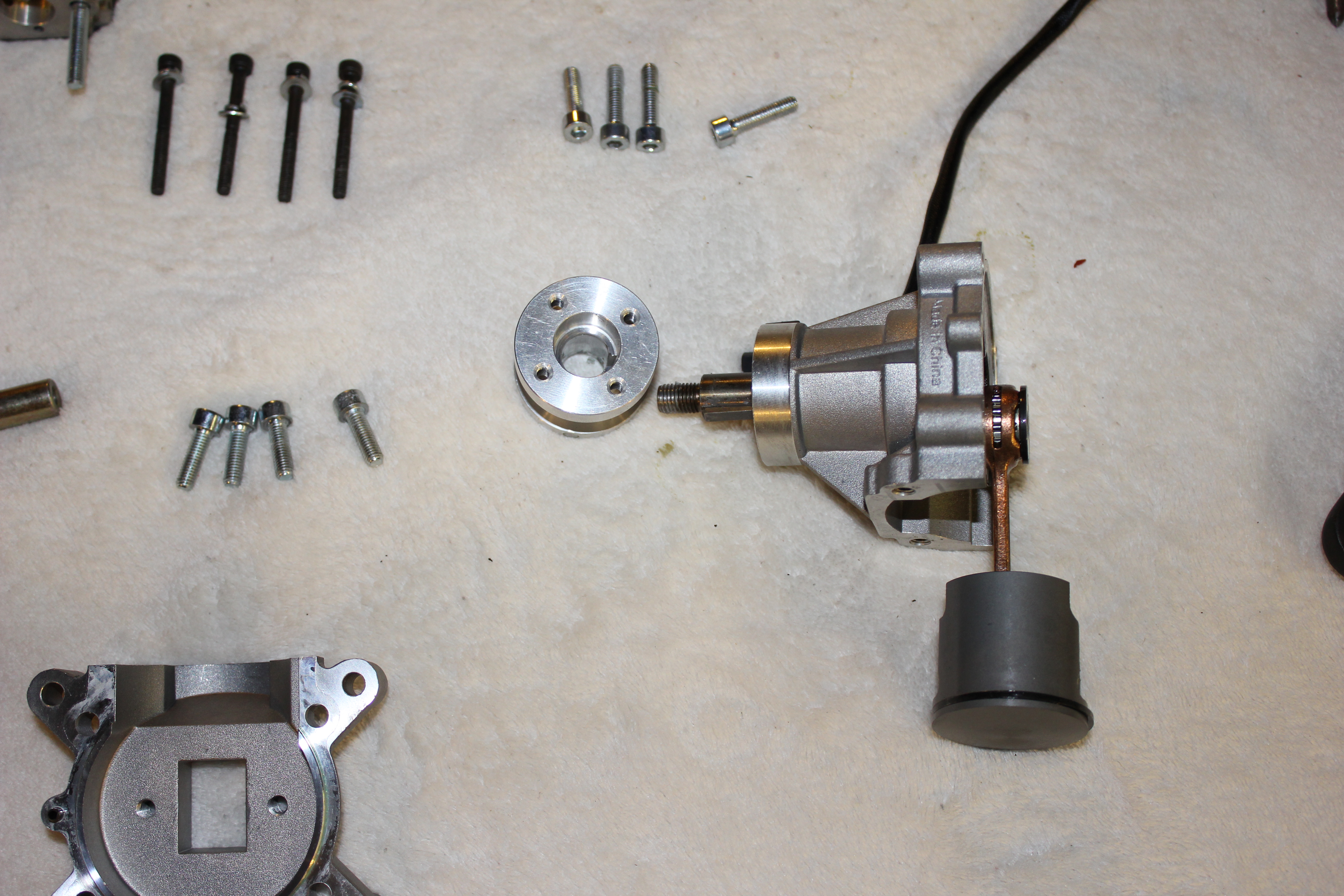 puller’s pin should be, so don’t worry about damaging the end of the crank. Here’s what’s left after pulling the hub.
7) Before the crankshaft will slide through the front and rear bearings, be sure to remove the key way that protrudes from the slot in the crank and put it in a safe place … it’s small and is easily lost. Even after removing the key way, it’s a bit of work to get the crank to slide out. Again, heating things up will help, but I’ve found that re-installing the 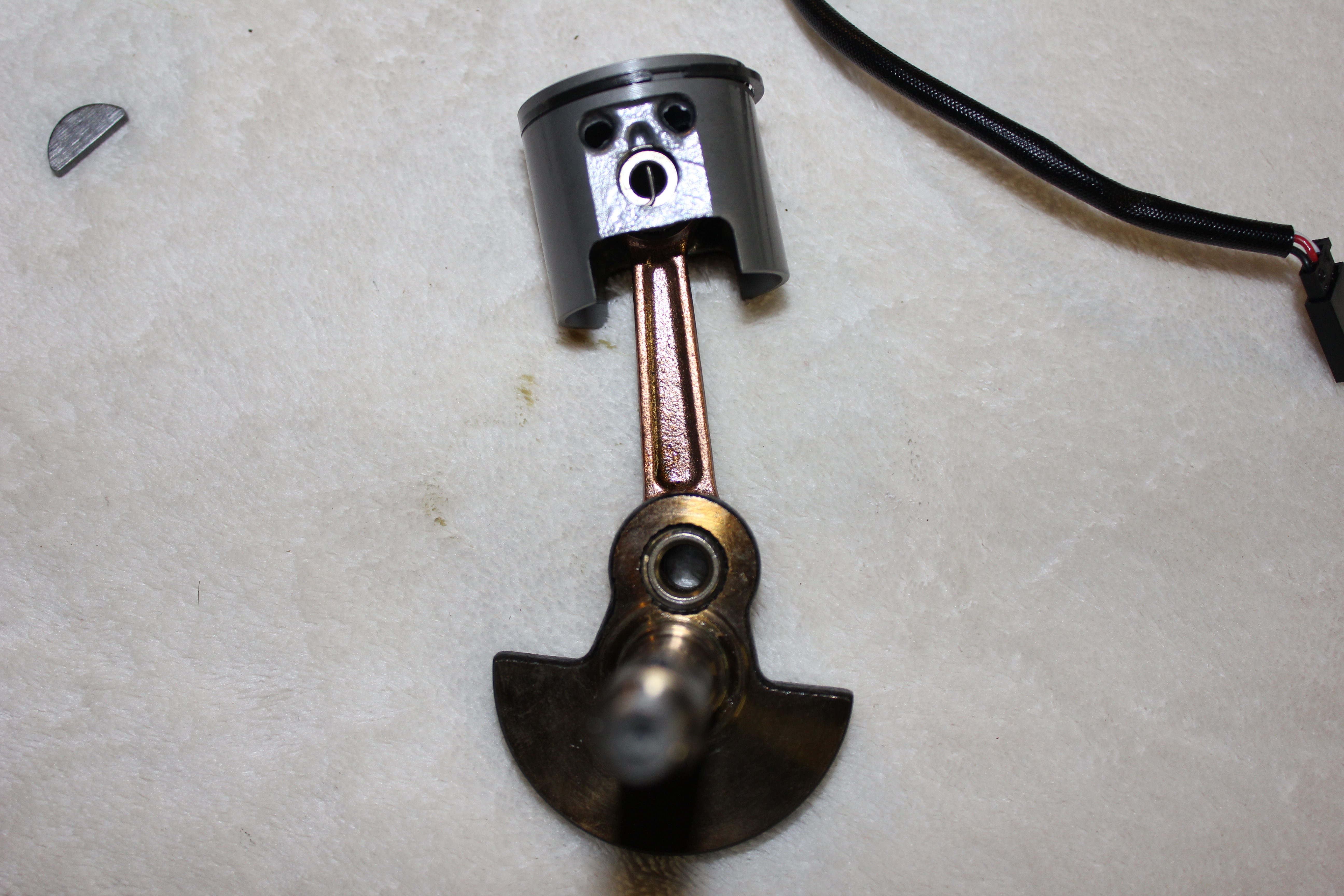 crank nut, placing the 11mm socket on the nut and gently tapping with the wooden handle end of a small hammer works best. Don’t get all whipped into a frenzy here and start smashing things. Little repeated taps should work just fine. Now our crank is free!
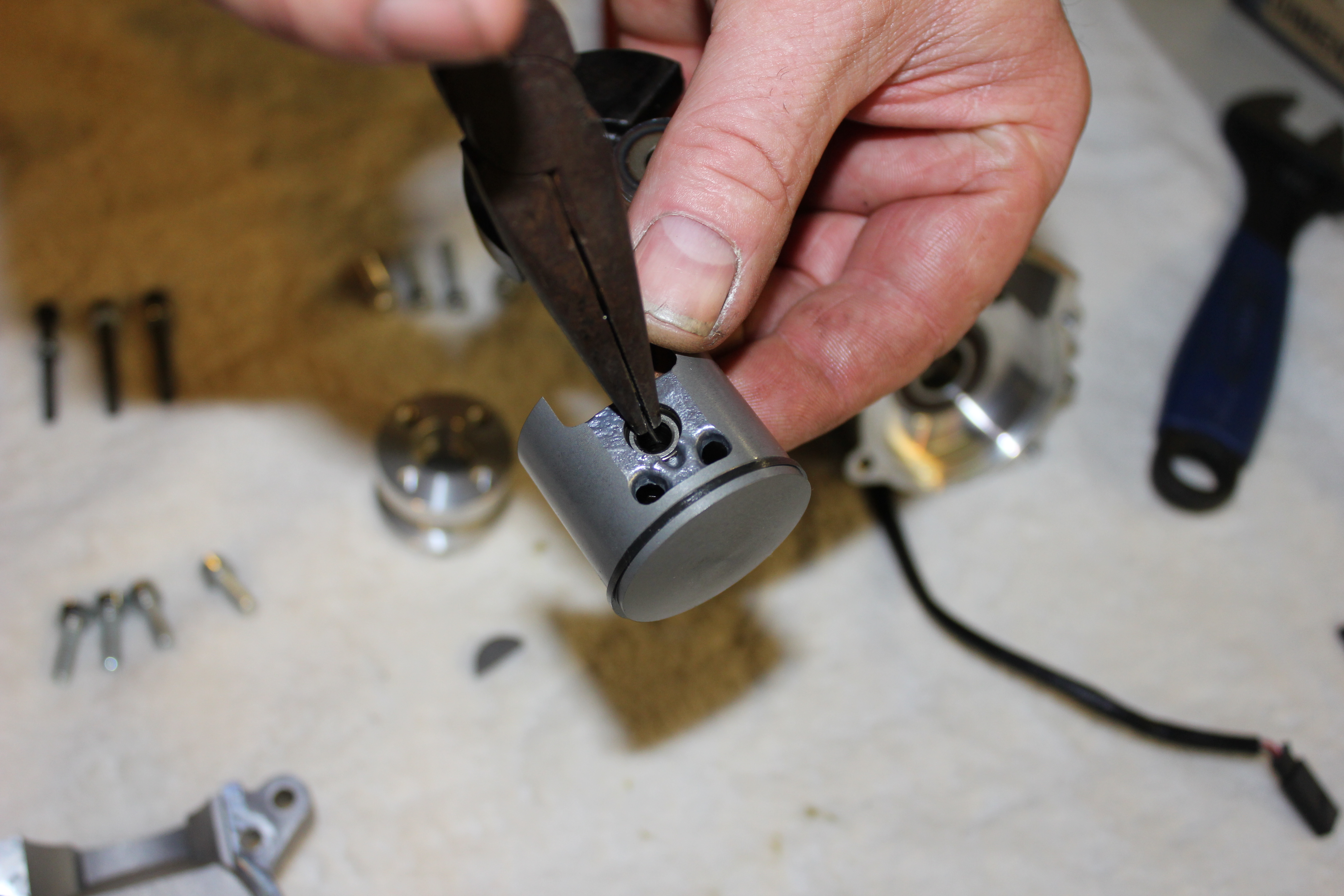 8) Now comes the little bit of delicate work concerned with this venture. Carefully insert the needle nose pliers into the opening in the top of the piston and grab the cross section of the retaining clip. Carefully rotate the pliers one way or the other (depending on which way the clip has been installed at the factory) and pull the clip out.
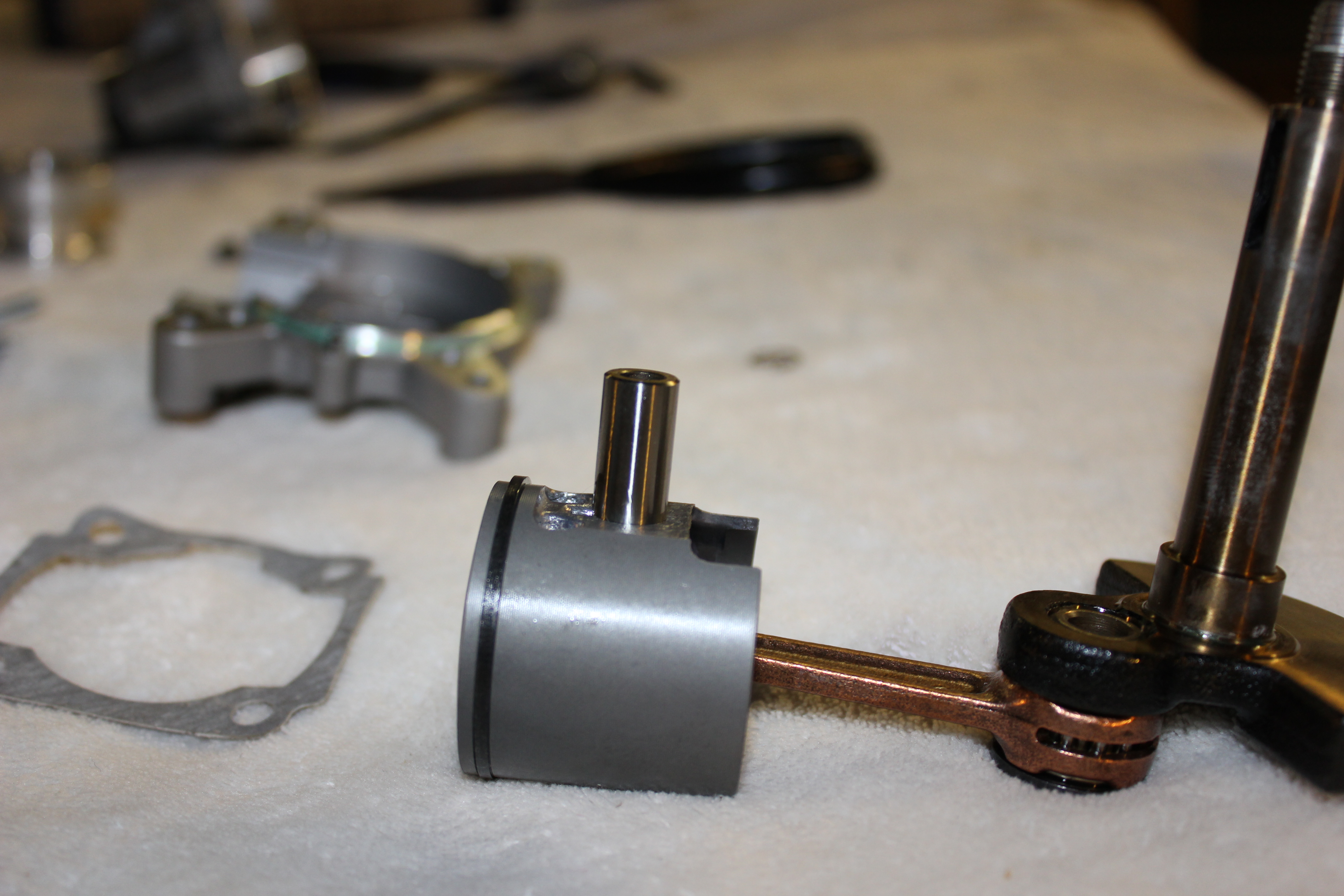 9) After getting just one of the two clips out, you should be able to push the wrist pin off of the connecting rod and out of the piston.
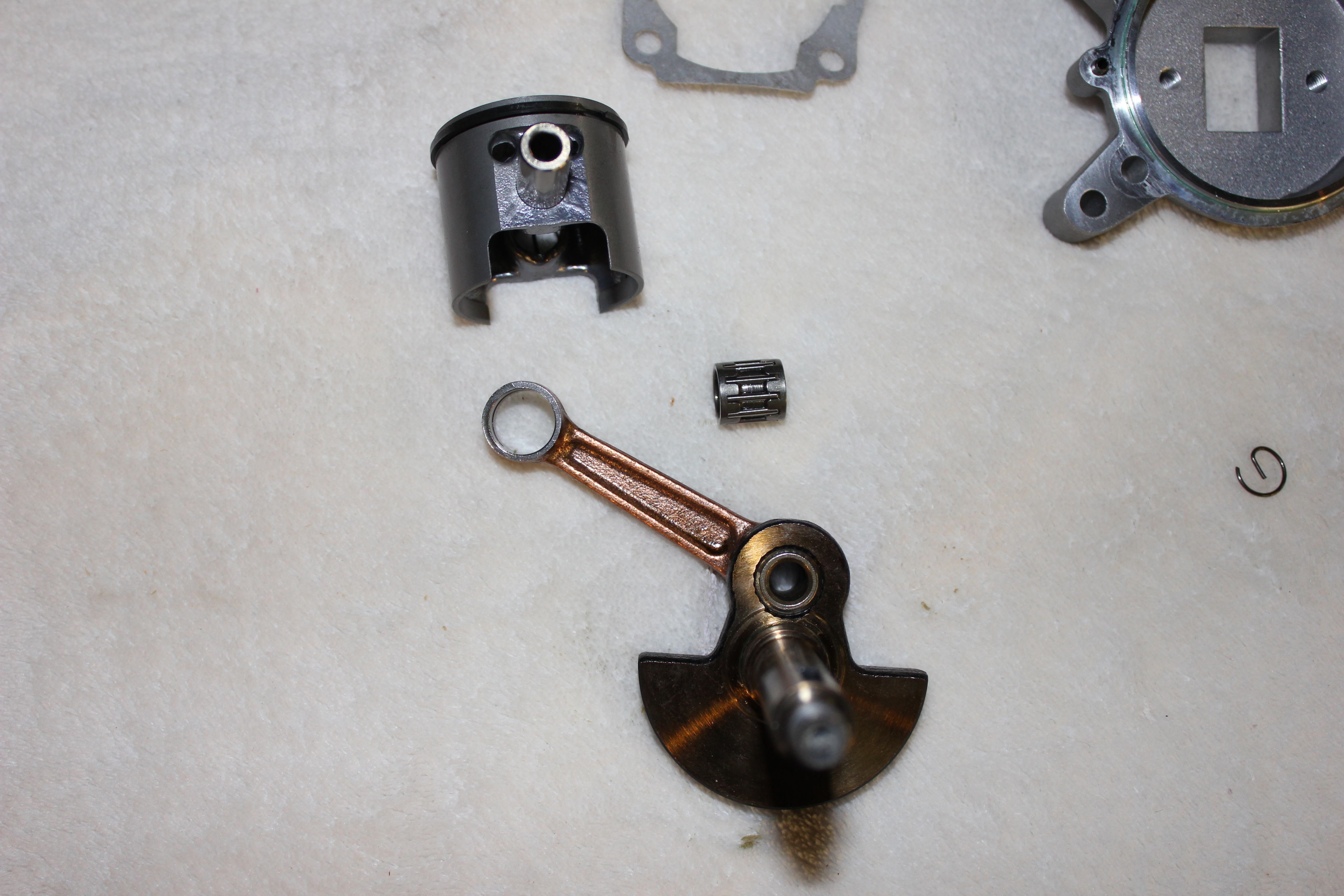 10) Once the rod is pushed clear of the bearing and rod, the piston should come off. Be careful not to drop the bearing. Here you can see the piston, rod and roller bearing as theycome apart with the retaining clip set to the side.
 11) Turning our attention back to the otherwise empty crank case, we can see the crank sensor for the ignition which is mounted so that it can read the RPM of the
magnet contained within the hub. Be sure to mark the sensor’s location if it is removed so as not to advance or retard the timing on the engine.
Re-assembling the motor is pretty much the opposite of what we just went through and while it isn’t really imperative to go through all the reference photos in reverse, there are a few tips and tricks to ease things along in the rebuild process. Starting with the crankshaft, be sure to coat everything with a light coat of light oil to aid in the parts sliding back together. It is also advisable to use oil on the hub adapter and cylinder head to piston areas. Remember to re-insert the key way on the end of the crank before pressing the hub back on the shaft. Don’t forget to re-apply an ever-so-small amount of high performance silicone to the flange of the back plate before screwing it back down, in addition to using thread lock on the screws. Be sure to re-install the piston in the same orientation which it was removed, using the pin we showed earlier as a reference. Before buttoning up the head, it is absolutely imperative that the lower gasket be replaced when re-building any motor. The bottom of the cylinder is tapered for the piston, but pinching the ring into the groove with two fingers greatly aids in getting the head back on properly and is finished off by thread-locking the four head bolts and tightening them down in a crisscross pattern. Once the reed valve, spacer and carb are re-attached, we’re pretty much back where we started.
Now that wasn’t so hard, was it? Like I said before, you need to have the proper tools and a good clean work surface to do this. We didn’t get into pulling the bearings as this was a brand new motor, but it’s fairly simple to do. My chosen method is to get the entire empty crank case good and warm with a heat gun and to press them out using a bearing press. It can get a bit messy with all the oil in the bearings themselves, but a few strategically placed rags will help. I hope that this little tutorial help negate some folks’ fears about splitting their DLE 30 open and I look forward to bringing you further installments of my motor maintenance series.
LINKS
HOBBICO hobbico.com, (217) 398-8970
