 Fly RC Magazine WE LIVE RC
Author:
Jim Onorato jimo@flyrc.com
Photographers:
Walter Sidas & Jim Onorato
Tow a glider—dust a crop
NEED TO KNOW
MANUFACTURER: The World Models Mfg. Co., LTD.
DISTRIBUTOR: Airborne Models, LLC.
TYPE: Sport-scale tow plane/crop duster gas ARF
FOR: Intermediate sport pilots
MINIMUM FLYING AREA: RC club field
PRICE: $649.99
INTRO
The World Models Piper Pawnee with its iconic canopy and top-side wing struts lets you bring a not so common model to your flying field. While I liked the way the many parts were packaged and identified, I found the high parts count to require more assembly time than the average ARF. Having said that, overall, I was pleased with the construction, quality of the materials used, finished look of the plane and I am perfectly happy with the way it flew. The Toughlon heat-shrink covering was wrinkle-free when I opened the box and has stayed that way ever since. I would have liked a top hatch for increased access to the internal equipment and ease of field assembly, but have decided that the few extra minutes needed for assembly at the field are a small price to pay once I saw this neat plane in the sky.
ASSEMBLY
The Piper Pawnee has a high parts count that includes many nuts and bolts. Fortunately, they are all packaged in plastic bags that are numbered to correspond to the numbered assembly steps in the instruction manual. This is a great help during assembly and you are better off if you don’t open any of the parts bags until you get to the step where they are required.
You may find it convenient to prepare the six aileron, flap and elevator servos and mount them on their respective servo hatch covers before beginning any further assembly. This involves bolting the heavy duty arms provided onto the round arms that came with your servos. The holes will have to be enlarged to accommodate the small socket head screws and you may have to drill new holes if the holes in the round arms don’t line up with the four holes in the heavy-duty arms provided. I centered all my servos, drilled pilot holes in the molded hatch covers then mounted the servos with the hardware provided with the servos. I also attached the extra-long rudder servo arm to my seventh servo.
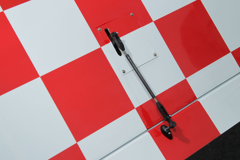
Next, the aileron and flap servos were installed in the wing panels. I used 24 inch extensions on the aileron servos and secured the connections with heat-shrink tubing. The leads on my flap servos were long enough to exit the root of the panel so no extensions were needed on them. The ailerons and flaps use pinned metal hinges that are already installed and glued in place so nothing needs to be done with them. I installed the four control horns in the ailerons and flaps then attached the pushrods. Each control horn consists of eight pieces so I installed them all in one sitting. The pushrods for the ailerons are slightly longer than the ones for the flaps so don’t get them mixed up. The pushrods do not use conventional clevises that you spring open to attach to the control horns. Rather, they use plastic clevises that get attached to the control horns and servo arms with small socket-head screws and lock nuts. The wing struts get installed next. Note that there is a left and a right strut and be sure to use thread lock on the socket head screws. I used canopy glue to attach the strut fairings to the wing.
The stab already has the covering removed in the gluing area and simply slides into a slot in the fuse. The fit between the stab and the fuse was so tight that, after making sure it was lined up properly, I glued it in place with thin CA on top and bottom. The metal hinges are already glued in the elevator halves so all you have to do is use epoxy to glue the hinges into the stab. I applied a little Vaseline on each pin to keep the epoxy from sticking to them. The two elevator servos get installed in the rear of the fuse on hatch covers just like the aileron servos. This is a nice feature as it keeps the servos out of sight with only the servo arms protruding from the side of the fuse. I used two 24 inch extensions and a reversing “Y” harness to connect the servos to the receiver. Since the reversing “Y” harness would not fit through the guide tube in the fuse, I placed it close to the receiver rather than close to the servos.
The hinges are already glued in the fin and rudder which gets epoxied into the opening in the fuse. The rudder is driven by a pull-pull system with the servo located up front. The instructions say to attach the cable to the rudder horn first in step #12 and later to the servo in step #16 but it is difficult to attach the cables to the servo arm after it is installed because the access hatch in the bottom of the fuse is quite small. I recommend you reverse the steps and proceed as follows: cut the supplied cable in half and insert each half through the holes at the rear of the fuse (you may want to tape the loose ends so they don’t get pulled into the fuse) then slide them in until they come out the hatch, next, attach the cable ends to the servo arm with the hardware provided and attach the arm to the servo, and finally, attach the loose ends to the rudder horns.
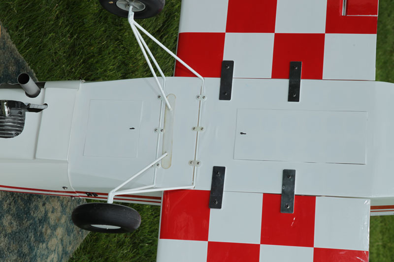
The scale tail wheel assembly attaches to the fuse with three sheet metal screws and is driven with springs attached to a fitting screwed onto the rudder. The painted main landing gear attaches to the fuse with six nylon landing gear straps after the covering is removed from the slots in the bottom of the fuse. Pilot holes drilled in the mounting plates have to be enlarged because the mounting plates are made of very hard wood. Also, be careful not to drill into the pockets that will contain the metal wing spars. The tires provided are inflatable but World Models does not make a fitting to inflate them and none is provided. I found a piece of rubber hose large enough to fit entirely over the tire valve and attached it to the air nozzle on my compressor and that worked out okay.
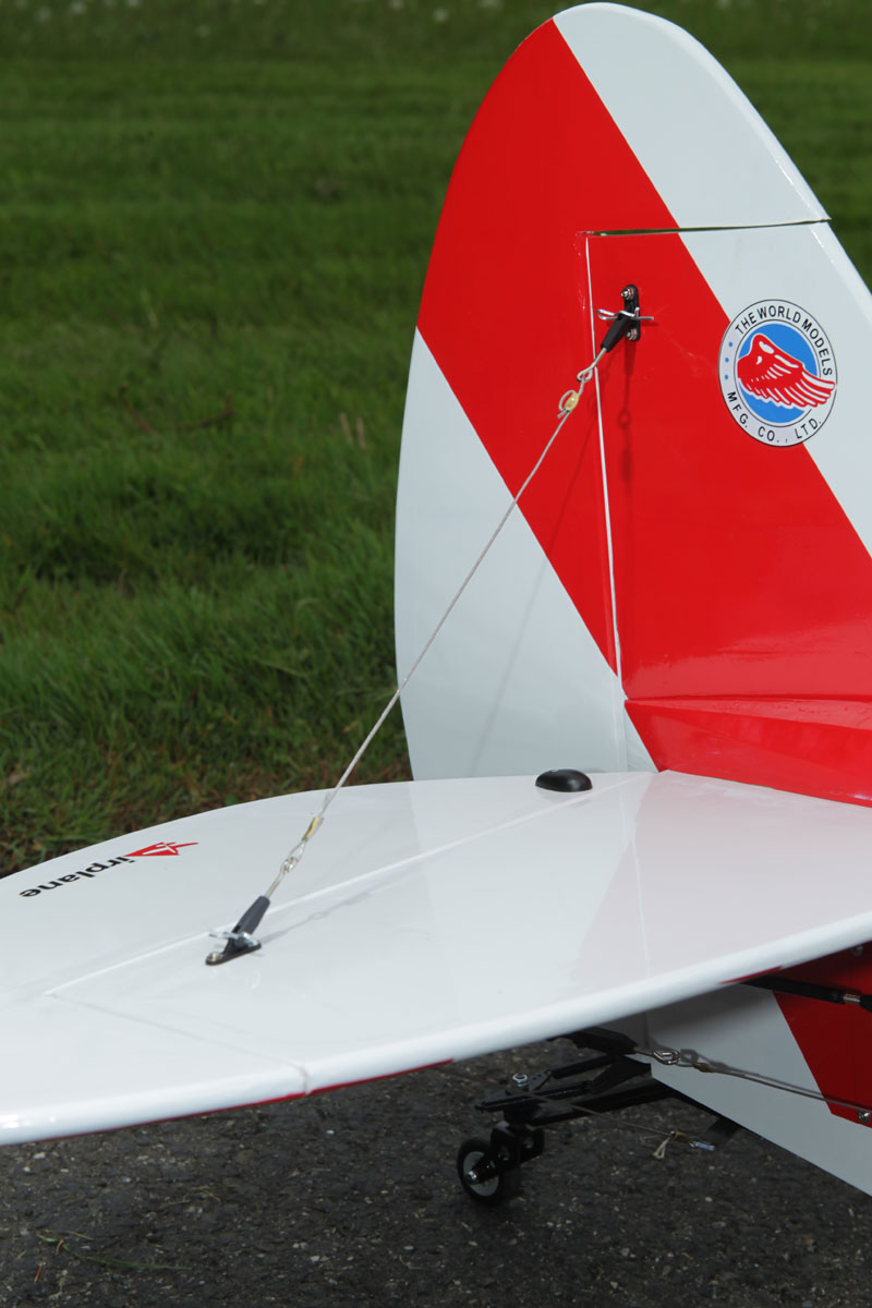
Flying wires are used on the Pawnee to strengthen the tail feathers. Small plastic mounts get attached to the stab and fin with small bolts and nuts through pre-drilled holes. The clevises on the ends of the wires attach to the mounts with body clips which, while not very scale-like, make adjusting the tension on the wires quite easy.
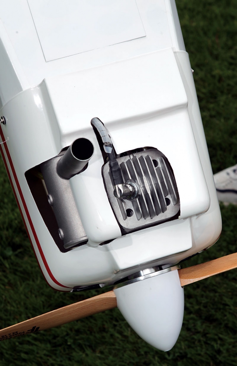
I used a DLE-55 gasoline engine for the Pawnee and mounted it inverted using the standoffs that came with the engine and hardwood blocks that were necessary to extend the engine the required distance from the firewall. I mounted the ignition module on top of the wooden mounting blocks and the ignition battery on the right side of the firewall. The fuel tank was mounted on the tray just behind the firewall as was the throttle servo and the receiver battery. I used a two line fuel system with a large DuBro fueller that I mounted on an aluminum angle fastened to the left side of the firewall. The vent line was routed out the bottom of the fuse.
A clear dummy cowl is provided to help you make the engine cutouts in the cowl and World Models has even marked the dummy cowl to indicate where cutouts are required for two different engines. Although the DLE-55 was not one of them, the markings were still very helpful.
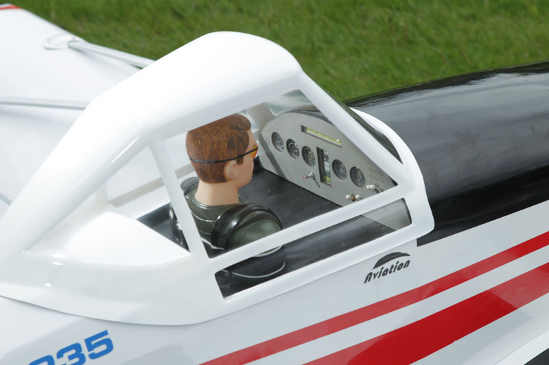
I added a small lite ply tray for the receiver in front of the rudder servo and attached it with hook and loop tape. The addition of the instrument panel, pilot and canopy completed the assembly.
 |
 |
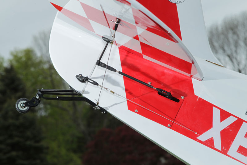 |
| The aileron servos are hidden in the wing behind a removable panel. The hardware, while more complicated than some, is very rugged. | The rear stab’s flying wires are installed. | The elevator servos is hidden in the rear of the fuselage. The rudder uses a pull-pull linkage and the servo is installed up front. The tail wheel assembly is very rugged and works well. |
 |
 |
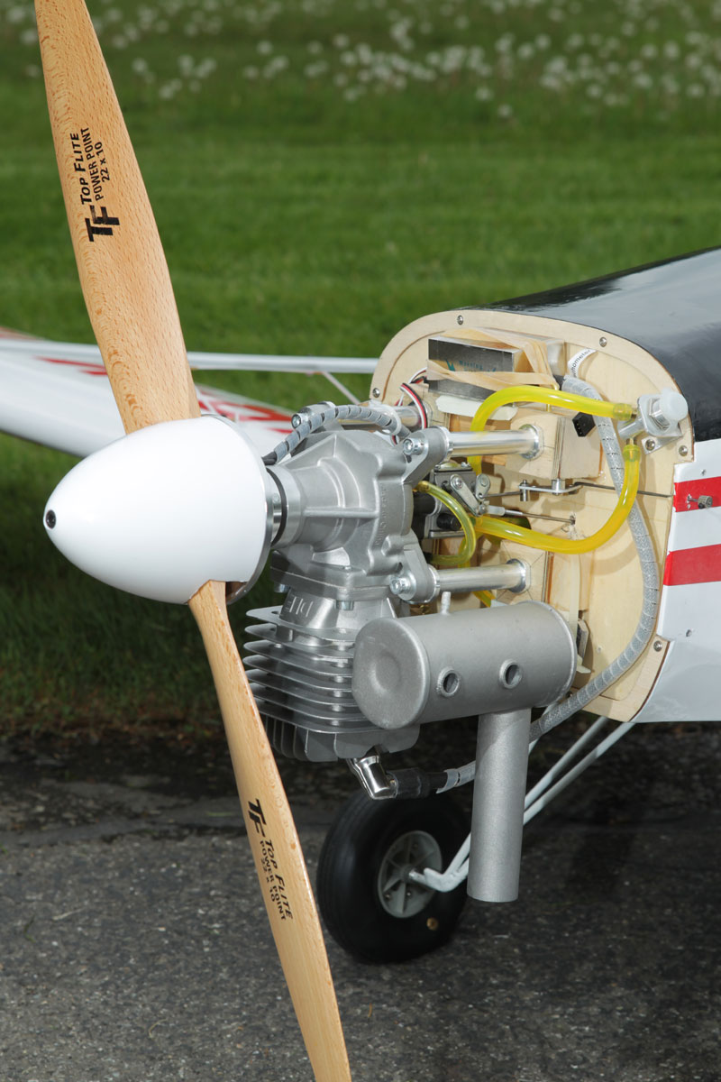 |
| The landing gear is attached to the fuselage via 6 tabs and 12 screws. You can also note the four metal tabs that attach the wing halves. | The cowl is nicely cutout to clear the engine. | Beautiful DLE engine installation. |
 |
 |
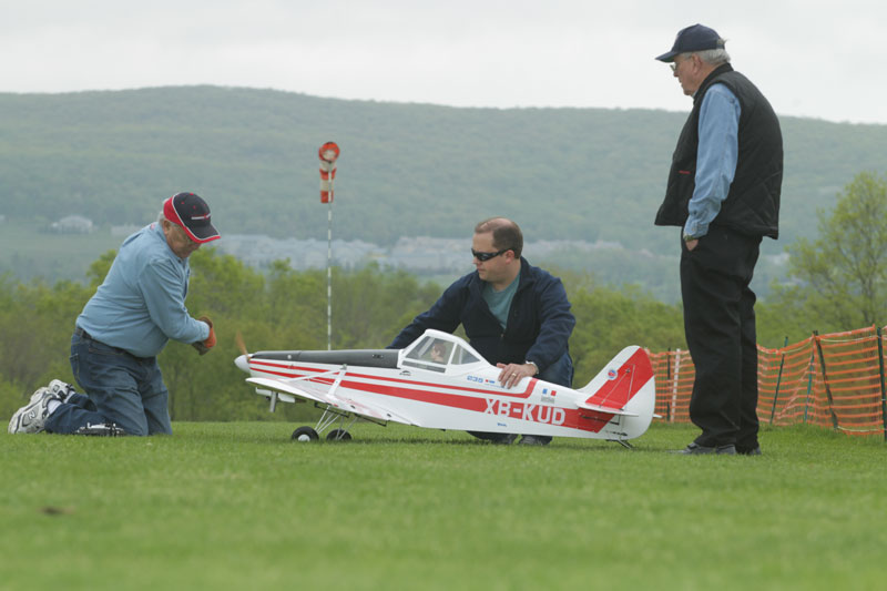 |
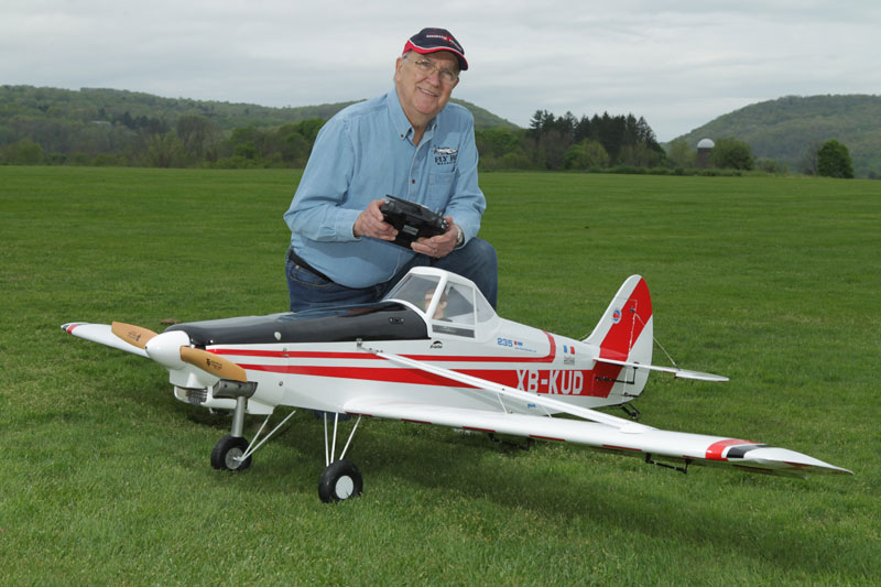
| Nice scale pilot with instrument panel. | Jim (the author) and the Pawnee ready for the maiden flight. | First start up of the new Pawnee |
