 Fly RC Magazine WE LIVE RC
This article was originally published in Fly RC’s March 2016 issue.
By Bob Benjamin
Recently I devoted several weeks of workshop time to determine just how far I could go with fiberglass-and- paint resurfacing and refinishing of a typical large foam/ARF electric powered RC scale warbird…in this case the 61” wingspan J-Power P-51-D available from Atomik RC.
My intent was to go all-out to fill and/or cover those exaggerated molded-in surface details that are typical of most models in this class, provide a new fiberglass-based skin to improve the durability of the standard-issue molded EPO foam finish and then add a traditional detailed, airbrushed paint finish to see how close I could come to creating the appearance of a built-up (non- foam) airplane without adding so much weight that the flyability of the model would be compromised. I did it, it worked and I learned a lot. Check out http://www. rcmodel.com/2014/07/finishing-those-foam- arf-rc-scale-airplanes/ for all the details.
While I was busy tempting myself by checking out Atomik RC’s entire line of foam ARF warbirds (and had already committed myself to the big P-51-D) I couldn’t help wondering what cool things I might be able to do with one of their Sonic Modell 74” span B-17’s. Check out atomikrc.com for a whole lot of good reasons I decided to stash the (very big) B-17 box under one of the work- benches in my shop and concentrate on learning everything I could about improving foam ARF’s by working on the P-51. I never quite managed to let myself forget that a six- foot B-17 was waiting in its box in the shadows under the table…but…I kept my promise to myself and left it there until the P-51 was finished, flown, evaluated and written up as the report I’ve already referred to.
If you have already checked out that P-51 feature, you know that I invested a LOT of time and a LOT of work on that conversion project. What should I do with this B-17? My wife, Teryl, who has been at my side supporting and encouraging my model airplane thing for a LONG time suggested that “That P-51 is a mind-blower… most modelers would never know it’s a foam ARF unless you told them, but most modelers might also be scared off by all the work you put into it. They’re going to be pleased that you showed that it can be done, and how, but isn’t there a simpler way to get the same sort of results?”
You already know my answer had to be, “No…but almost. Yeah, you could come pretty close” … and that’s when I decided to use this B-17 to show how far you can go with scaling out/improving a foam ARF without getting into the whole resurfacing-fiber-glassing-painting deal. Here’s how I did it.

Here’s a quick preview of what’s coming. Before photographer Gary Ritchie took the in-flight shots I’ll include at the other end, he grabbed this image of your columnist with the B-17 all ready to go. At this point the airplane already had half a dozen flights logged right there at our Puget Sound Silent Flyers field near Olympia, WA. Gary’s close-up focus makes that house in the background appear WAY closer than it actually is…but even if it were like that we’d be OK with our neighbors of nearly twenty years of flying here, because we are and always have been ALL-ELECTRIC FLYERS. My well-broken-in flying hat only LOOKS that old, though.

1 As it comes out of a very big box there is a whole lot of pre-assembly done on this model airplane. Here you can see the bottom surfaces of both wings – the right panel is in the foreground – with just about everything already put together. Not only are the engine nacelles pre-molded in as part of the wing panels, all the servos with extension cables attached and in place as well as the motors and ESC’s are in place. As this model is fitted with (four) brushless motors, it’s necessary that there be a dedicated ESC for each of them. See those black panels (with big air passage openings) near the leading edge just inboard of each nacelle? The ESC’s are slip-fitted into cutouts in the EPO foam wing right under them. We’ll decide in a bit what, if anything, I ought to do about them. I’m sure you also noticed that the retractable main landing gear units are already assembled/mounted in place. You could bind your receiver, plug ‘em all in and they would work RIGHT NOW. If I were planning to do an all-out resurface-and-refinish job on this model as I did on the P-51, my main concern right away would be to pull everything you see here apart so I could start filling, priming and sanding…but…we’ve already accepted the idea the factory fresh foam finish is here to stay, so the question becomes, “What else can we change to improve the appearance and what’s the best way to do it?”

2 Here’s a closer look at the bottom/right wing panel. Once we accept the decision to keep the molded-in detail (and work on disguising it with an artful paint job) we can focus on whatever other details we want to improve. Those open channels/grooves where the servo, light, throttle and RLG cables are recessed into the foam surface don’t need to stay like that, nor do the servos themselves. The ailerons servos came pre-installed with real mechanical hinges and they look OK, so I’ll leave them that way. The flaps, on the other hand, are mounted/hinged with a strip of tape. My first thought was, “That has to go…” but in fact they work the way they need to and won’t look out of place on what’s going to be a really busy wing under surface.

3 Let’s start “fixing” with those servo cable channels. I cut some 1/2” strips from adhesive backed aluminum tape from the hardware store and trimmed them to fit the various cable openings I want to disguise. The edges I created are not in any “scale location”, but when all the tapes are in place and painted, they will look as if they are supposed to be there.

4 We have got to do something about those exposed aileron and flap servos. At least they’re recessed flush with the wing surface so I don’t have to make decisions about cutting into the wing to keep them from looking like mechanical warts sticking out of the airplane. As it turns out all I have to do is draw out a pattern for a cover plate with an opening/slot for the servo output arm and make four of them from lithoplate (or aluminum roofer’s flashing). Deluxe Materials Foam 2 Foam is my adhesive of choice here… it’s guaranteed “foam friendly” and provides a fi rm, slightly flexible bond between the foam structure and the metal cover plates.
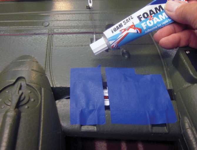 5 Foam 2 Foam is also my choice for keeping those ventilated ESC covers in place. I wasn’t entirely comfortable that the original adhesive would “stay stuck” in flight. I got ahead of the camera a bit here…that blue masking tape is holding the covers firmly in place while the adhesive sets.

6 Back on top. Some of that over-enthusiastic surface detail is easy to deal with. There are five fuel tank access covers (gas caps) on the upper surface of each wing of a B-17-F. The crude, oversized molded-in rings that represent them on this ARF are just too chunky to ignore, so I sliced them all off flush with the wing surface with a sharp/new razor blade. Wait and see what I’ll do with them next.

7 In place of a more involved fiberglass-skin- based surface treatment on this airplane, I’m keeping it simple by using Deluxe Ma- terials Foam Armour one-step surface reinforcement and finish base formulated for foam ARF models just like this one. Here I am beginning the job of brushing a generous (wet) coat of Foam Armour over the entire airplane. (You may occasionally find that Foam Armour has thickened just enough in the container that it becomes difficult to brush out smoothly. That’s easy to ? x. On ANY application you can thin the material as necessary with plain old water to get a brushing consistency you’re comfortable with.)

8 I let my coat of Foam Armour run right over and onto the narrow seams at the edges of all those sort-of-transparent window insets. Since there’s no detail inside to worry about hiding, the slightly clouded finished appearance I’ll get on the windows hurts nothing and actually enhances the camouflaged “working airplane” look I’m trying to achieve. Right now you are looking at the entire airplane with that single finish will go away…

9…and the Foam Armour surface will look like this after a few hours of drying time. Can you see how the material has self-leveled and created a smooth surface that does a good job of beginning to hide that “spotted-foam finish”? It also does a fine job of blending in the replacement “gas caps” I made from more of that adhesive backed aluminum tape I used on the bottom of the wing.

10 One of the obvious details that got left out on this particular ARF rendition of a B-17-F is the characteristic light gray paint job on the bottom of the airplane. The model will fly OK if you leave it all olive drab the way it comes out of the box, but this step will make it look WAY better. Although this B-17 is made of EPO (expanded poly olefin) which will accept just about any type of paint finish you might want to use, not all foam ARF’s are so fortunate. To show how easy it is I chose to use ordinary craft store acrylic paint (in those little plastic bottles). Everybody names their colors differently. Since we’re not going to be concerned with scale judging for color accuracy, just pick a color that looks close to you. I started with the bottom of the right wing…

11 …and went on to the fuselage. I’m using my Badger double-action artist’s airbrush to get the control I need to “free hand” the camo color separation along the sides of the fuselage. BTW: Denatured alcohol is the best way to thin craft store acrylic so you can airbrush it…don’t be afraid to thin it A LOT if you have to. Keep thinning until it sprays properly.

12 Same game on the top of the airplane. Those new gas tank covers are among the various places on the model that are going to need some touch-up of the original olive drab base color. Another BTW: It’s going to be difficult to get an exact match to the pre-existing color on the model . This would be the case on any ARF you might work on. In this case “close enough” is OK…I’ll say more about that later.

13 See what I mean about the less-than- exact color match (and this was the best match of five different shades I tested). Don’t get all worried about precise color matching here…not only are we not concerned with scale judging, we also need to remember that this is a model of a COMBAT airplane. It got fixed and patched and fussed into “one more mission” so often that there might have been very little factory- standard paint left on a given full scale subject.

14 Same game on the tail group. Assembling the horizontal and vertical tail parts per the instructions left noticeable gaps along the joining edges. I filled them all with a careful “fingertip-smooth” application of Deluxe Materials Roket Gel and used the airbrush to begin camouflaging the repair job.

15 Now it’s time to get “down and dirty”. I mixed up a special batch of “dirt” color…sort of a grimy gray-brown…to represent exhaust, oil stains and mud. With a single batch of color I can control how dirty/oily any particular part of the airplane gets by airbrushing on just a little for a light smudge or a lot for an oil leak or exhaust stain.

16 More of the same. If you have ever had a good look at a big airplane with multiple engines (especially radials) out on the wings, you’ll already know that the entire nacelle and ALL of the lower wing surface behind each engine gets DIRTY. After a couple of missions a B-17 is going to appear almost black there. Don’t try to put all the staining on in one shot, though… sneak up on it as I’m doing here and replicate the look of a sequential, layered buildup. A general rule for airbrushing exhaust/dirt/weathering is that less is almost always better.

17 The main LG wheels are going to get just as grimy as everything else behind the engines. Don’t worry about over spraying onto the tire…it’s gonna’ be dirty too. Notice the other main wheel/tire in the background. That clean-out-of-the-box plastic really sticks out, right?

18 The B-17 had an exhaust- driven turbo- supercharger mounted in the nacelles behind each engine. The moldmaker for this particular ARF did an OK job of representing them, but we need to make each one look as if it’s mounted within an opening in the sheet metal cowl, made of various grades of steel that discolor from heat in operation and often show a touch of oxidation (rust) as well. So far this one is still the overall belly-gray you saw me add in steps 10 and 11.

19 Here I want to represent the sharply cut-off appearance of the dark inside of the cowl as defined by the sheet metal edge on the full scale B-17. I’m brushing dark gray into the turbocharger cutout using the molded edge of the simulated cutout to define the paint line. I’ll add more detail here later.

20 The top of the airplane gets dirty, too. I’m using more of the same bottle of “dirt” paint to fill in every place where the airflow would naturally concentrate any stray exhaust or oil spray against the outer surface of the airplane. That’s about all the space we have for this first installment, but be sure to check out the finale of this project in a future issue of Fly RC.
