 Fly RC Magazine WE LIVE RC
Fly RC Magazine – June 2012
Hangar 9 Tiger Moth 20cc
Fly RAF’s Primary Trainer in Giant Scale
By Jim Onorato
Photos By Walter Sidas & Jim Onorato
ASSEMBLY
The 60-page Tiger Moth assembly manual, which can be downloaded from Horizon Hobby’s web site, contains step by step instructions in four languages. Along with the written instructions, there are numerous detailed photos and symbols to guide you through the assembly process. An assembly symbol guide and full size drawing of all the fasteners as well as a complete list of required and optional items and a list of required tools is also provided. Since all of the fasteners are metric, you will need several small metric hex wrenches, nut drivers and metric drill bits of the sizes spelled out in the instructions. #1 and #2 Phillips screw drivers, a crimping tool and blue thread lock will also be required before you begin assembly. Now, with that out of the way, let’s get started.
Assembly begins with the undercarriage which consists of five parts plus the axles and wheels. Be sure to use thread lock on the bolts that thread into the installed blind nuts. Those that thread into elastic stop nuts obviously do not need thread lock. The axles and wheel collars are hidden within the wheel assembly and covered with hub caps to maintain the Moth’s scale appearance.
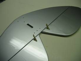
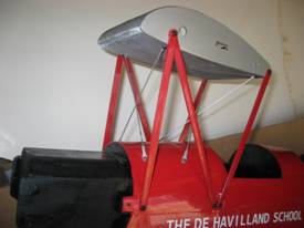
The dummy fuel tank forms the center of the upper wing and is held rigidly in place with six cabane struts and four support rods. Check the blind nuts on the sides and bottom of the tank to make sure the threads are clear before you begin assembly. The 4mm blind nuts on the sides of my tank were clear but I had to run a 3mm tap in the blind nuts in the bottom to clear them of residual paint.
All of the control surfaces on the Tiger Moth are pre-hinged. The elevator is controlled by two servos…one for each side. The manual shows a one-piece elevator and calls for drilling holes for the control horns but my plane had a two-piece elevator with all the holes already drilled. Consistent with the one-piece elevator shown in the manual, the manual calls for the need for electronic mixing or the use of a JR Matchbox to ensure that the elevator servos operate properly and do not bind or “fight” each other. I used a Matchbox to make sure both sides of the elevator worked the same even though my plane had a two-piece elevator.
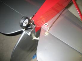
Holes for the rudder control horns were also already drilled so I installed a control horn on each side of the rudder for the pull-pull system and held them in place with the nuts and bolts provided. The fin/rudder keys into the stab and is fastened with two M3 bolts. The ones provided were too short so I replaced them with longer ones. Just make sure the bolts are long enough to engage the blind nuts installed in the fin. The assembled tail feathers are then attached to the fuselage with four metric screws and braced with two metal braces on the underside of the stab. The tail wheel assembly gets bolted to the rear of the fuse and is driven via two springs attached to steering horns located near the bottom of the rudder. Be sure to use thread lock where specified.
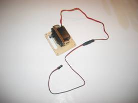
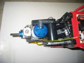
The two-piece composite engine mount provided gets attached to the firewall with four 4mm bolts. Again, I ran a 4mm tap through the installed blind nuts to make sure they were clear. I used the suggested Evolution 26GX gas engine and installed it 5 1/4 inches from the firewall as specified. A JR DS821 sport digital servo was used for the throttle and was installed on the servo tray located in the front of the fuse under the servo access hatch. The 1/16 inch throttle pushrod slides through a pushrod tube and is connected to the engine with a ball link and to the servo with a brass pushrod connector. The ignition module was attached to the lower part of the firewall using the hardware provided with the engine. Blind nuts that match the bolt pattern of the module supplied with the Evolution engine are already installed in the firewall. I inserted the ignition module’s LED into a hole I drilled in the forward instrument panel so I could see when the ignition was turned on. I added a third line to the assembled two-line tank for filling as I didn’t want to cut an opening in the scale cowling for a fueler. The third line exits the rear of the cowl and gets plugged after fueling.
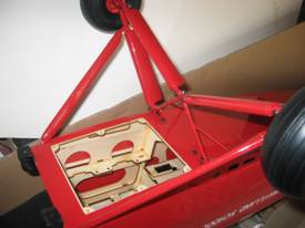
I used JR charge switches for the radio and ignition system and mounted them in the cutouts already made in the floor of the forward cockpit. The receiver, Matchbox, receiver battery and the ignition battery were all attached to a plywood tray with hook and loop tape and the completed assembly was installed on the rails under the access hatch. Two elevator servos and the rudder servo get installed on a plywood tray that is also located under the access hatch. The elevators are connected to their servos with long metal pushrods and the rudder is operated through a pull-pull cable setup. Make sure you have the throttle set up properly because, once the two plywood trays for the receiver, batteries and servos are installed, the throttle servo will be inaccessible. Once you have checked everything out, you can install the access hatch cover and proceed with the installation of the cowl.
It will be necessary to trim the cowl to clear the carburetor if you use the Evolution engine. This is not a big deal as all that is required is to remove part of the internal flange around the large opening in the front and cut out a horizontal oval below the spinner opening. I also made a large opening in the bottom to allow cooling air to exit the cowl. No other openings were required as the wrap-around Evolution muffler fit completely within the cowl. The cowl is held in place with four bolts that thread into pre-installed blind nuts. The fuselage was completed with the addition of the dummy oil tank and the two wind screens all of which were attached using silicone adhesive.
The Tiger Moth has four wing panels with ailerons in the lower wing only. These are controlled by separate servos mounted on servo hatch covers that already have the servo mounting plates installed. 12 inch extensions are required to bring the servo leads out to the roots of the wing panels. The aileron control horns do not utilize back plates and through bolts but are attached with sheet metal screws. Be careful when drilling the holes for mounting the horns so you do not penetrate the top surface of the aileron and be sure to apply a few drops of thin CA to the holes to harden the wood. Short 4-40 pushrods and clevises are used to connect the horns to the servos.
Installation of the wire rigging is probably the most time consuming part of the Tiger Moth’s assembly and a good crimping tool is an absolute necessity to ensure success. I found it helpful to take a few preparatory steps before installing the wings as called for in the manual. The rigging attaches to twelve brass clips.. three on each wing panel… and I found it much easier to install these clips before the interplane struts were installed. Each panel has two predrilled holes adjacent to the interplane strut locations. The bottom wing has a third hole located at the leading edge at the root and the top panel has a third hole located at the trailing edge near the root. Once the clips have been installed, you can install the wing panels and interplane struts per the instructions. You can also save some time by preparing all twelve rod ends and clevises at this time. Since you will need to tension the rigging after it is installed, you should only thread the clevises onto the rod ends a few turns so they can be tightened later. The wing panels slide onto aluminum tubes and are held in place by bolts at the root of the panels. These bolts thread in from the bottom of the fuse and dummy tank and are much easier to install if the plane is inverted with something supporting the center of the top wing (because of the dihedral). Make sure the panels fit tightly against the fuse and dummy tank or else the bolts will be difficult to insert. The Tiger Moth has spreader bars that are located where the rigging wires cross. My plane had two identical bars but the left and right hand bars are different. I had to drill two additional holes for the wire rigging in one of them to keep the wires from curving as they entered and exited the rod.
That completes the assembly of the Tiger Moth but there is one additional step. Wing transport frames are provided to facilitate transport once the wings are removed. These consist of three plywood pieces that you bolt together and are held in place with rubber bands.
Image Gallery
 |
 |
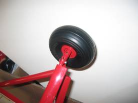 |
| Two piece elevator with all holes drilled | The dummy tank is firmly secured to the fuse with six cabane struts and four metal rods | The axle is inserted into the undercarriage and secured with a set screw keeping it completely hidden |
 |
 |
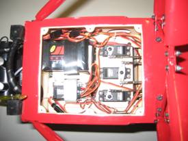 |
| The underside of the fuse shows the radio/servo area and the assembled undercarriage | The aileron servos mount on the servo hatch covers that already have the servo mounts installed. Each servo requires a 12 inch lead extension that is secured with heat shrink material | The receiver, Matchbox, batteries and tail feather servos are all located in the access hatch under the front of the fuse |
 |
 |
|
| Looking at the underside we can see the muffler, ignition module and gas overflow line | The tail wheel is driven through springs attached to the rudder. Also note the elevator pushrods and stab brace |
Links:
Evolution
Hangar 9
Horizon Hobby
JR
Spektrum
Zinger
