 Fly RC Magazine WE LIVE RC
Slide in tray…so easy!
Words And Photos By Kevin Siemonsen
I was asked by a fellow RC’er to assemble his 3W Extra 330. Being an accomplished modeler with enough experience that I actually feel old when I think of it … I was more than happy to oblige. This particular 3W is a fiberglass fuselage with foam core wings and tail. The plane had a high level of completion, was covered, painted, canopy and cowl installed. Like I said, many, many years of model building/ fabrication and considering the level of completion of the 3W Extra, I figured it’d be a snap. That was … until the guy decided he wanted to go electric. I have tons of experience with large gas models, but this was going to be a first for me.
ASSEMBLY
 Planning for the build proved to be a little challenging. The problem with any conversion is component location. There are some givens that remain consistent like most servo mount locations and obviously the motor
is going on the front, but that’s about it. I started by installing the servos and linkage installations in the horizontal stabilizers and the wings. I then mounted the big Hacker up front on the molded fiberglass motor mount. The directions are vague so basically the motor is spaced and centered so the spinner back plate is centered at the front of the cowl. I installed some two-inch aluminum stand- offs to get the adequate spacing and bolted in the motor. The big-ole Castle speed control was neatly mounted on the side of the fiberglass motor mount for good cooling.
With some of the “known’s” out of the way I could then start to pinpoint where other components would be mounted, keeping CG in mind. My goal was to have the main battery packs located where they were easily accessible through the canopy hatch. I then surface mounted the rudder servo in the tail and used a short push- pull linkage.
To counter the additional servo in the tail I mounted two 2S 5000mAh LiPo radio ba eries up front on
the fiberglass motor mount opposing the speed control. The receiver was centrally located in the fuselage belly, leaving the heaviest and most critical main power system batteries. With the plane pre y much fully assembled I was able to locate exactly where the batteries had to go.
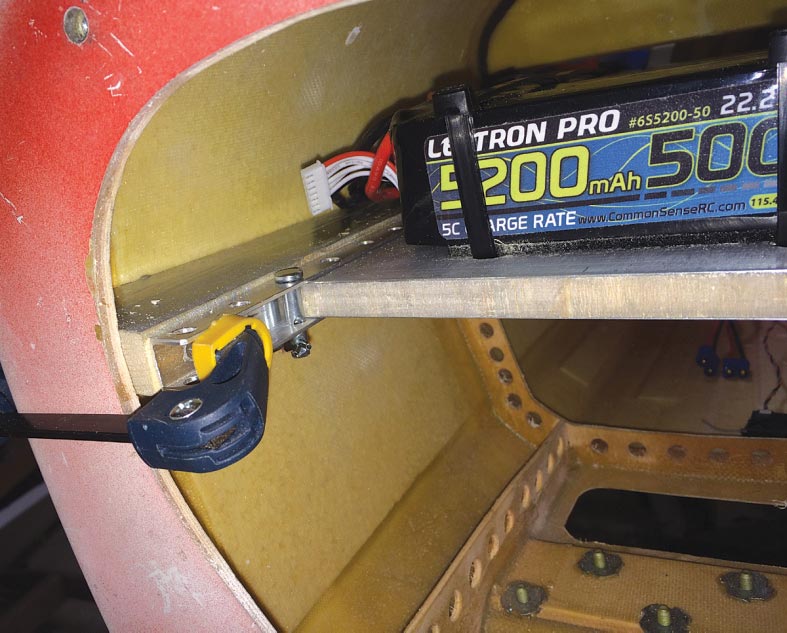
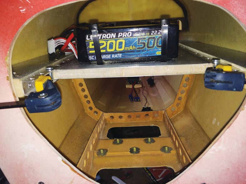
Unfortunately for me, the batteries had to be located far forward in the fuselage, making it difficult to access them and the fact there is a spar in the way screwed things up even worse. I pondered over what to about this for a few days before coming up with a slide-in ba ery tray idea. A slide-in tray would enable the batteries to effortlessly slide in or out and by making it adjustable it would be possible to tweak the CG for desired flight performance.
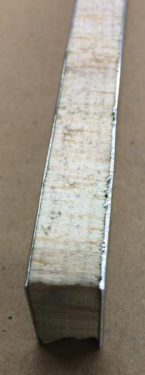
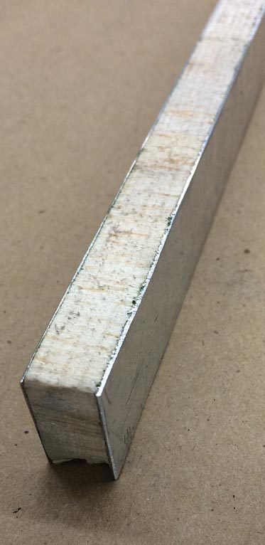
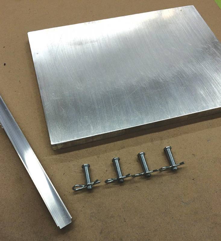
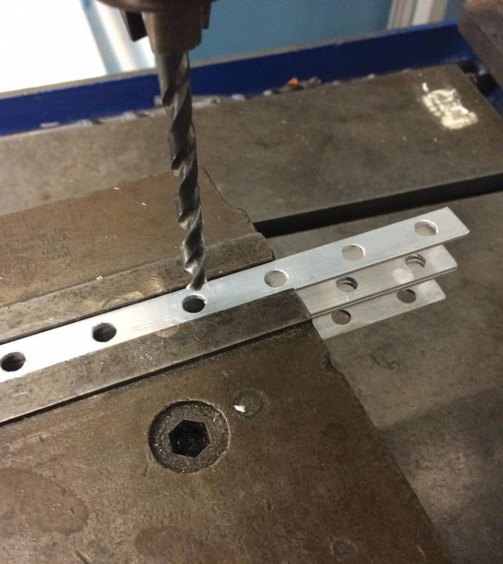
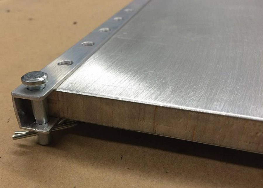
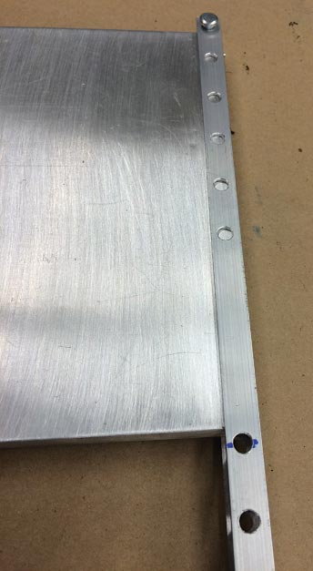
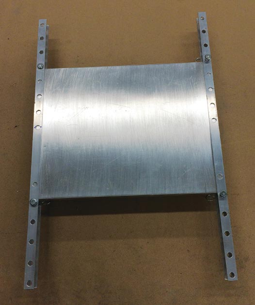
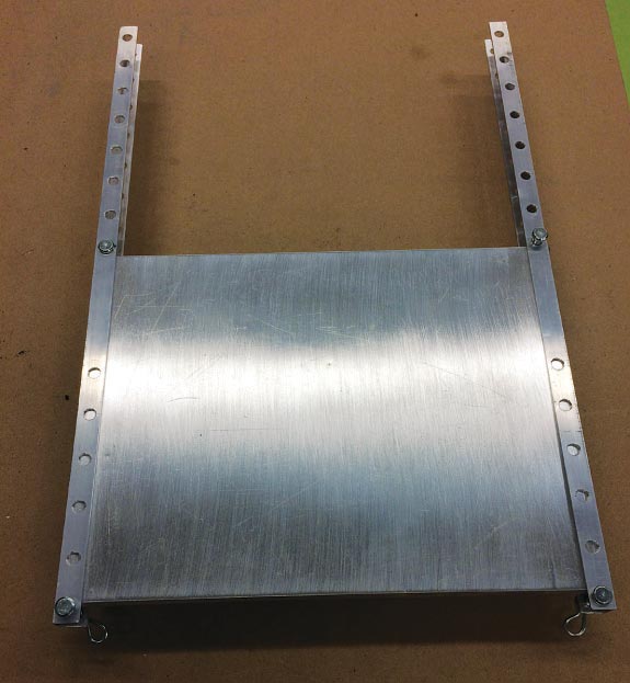
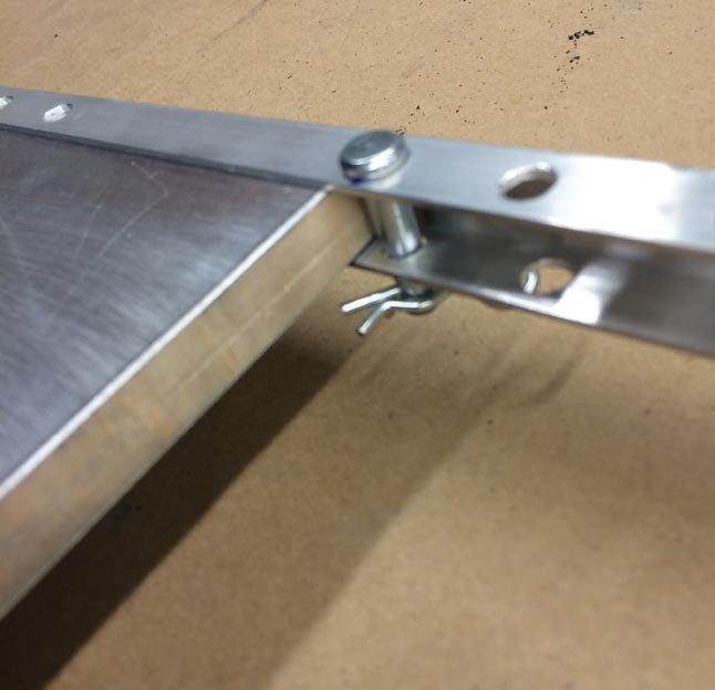
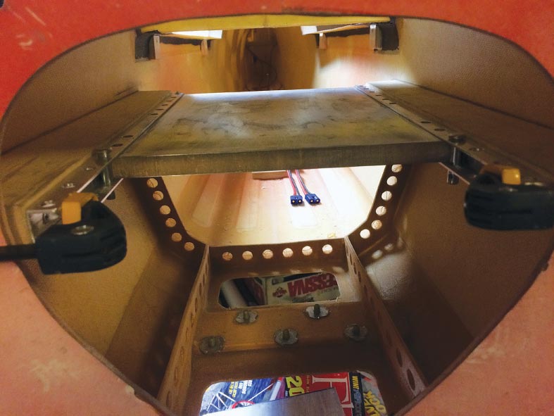
What I ended up doing was buying some 1/2-inch aluminum “U” channel from the hardware store. I cut two 14-inch lengths and then proceeded to drill a series of 1/4-inch holes one inch apart down each length of rail. I had a sheet of 1/2-inch balsa cored aluminum sheet. I took into consideration the width of the fuselage and the physical size of the batteries when coming up with dimensions for the battery tray plate. I used 1/4-inch thread-less pins and co er pins as a means to “lock” the tray in position within the rails by installing them into the holes located in front and behind the tray. I then fastened each rail to a block of hard wood that would act as a filler between the aluminum rail and the interior of the fuselage. I failed to mention that the interior of a 3W fuselage is entirely void of structure except for a small former between landing gear block and main spar. This is why the hard wood had to be shaped to conform to the interior fuselage sides, be parallel and the correct spacing for the battery tray. A hearty layer of Shoe Goo does an awesome job bonding the assembly into position. It might appear to be an overly robust installation, but keep in mind that the flight batteries are relatively heavy and it’s very important to try keep them in place in the event of a hard landing or crash.
THE VERDICT
Electric conversions are becoming more popular especially with big planes and the availability of moderately priced power systems. I got the chance to test fly the 3W Extra and was thoroughly impressed with the outcome. With the slide-in battery tray I was able to easily side batteries in and out of what would otherwise be a major hassle. I did end up moving the batteries forward an inch because it flew slightly tail heavy the first flight.
The ability to tailor the CG for a desired flying style is huge, especially when you consider no tools are necessary and without tools you dial the plane for IMAC or 3D. I am super happy with how clean the installation is and in the event I build another large electric plane, I will definitely incorporate an adjustable battery tray in the build. Happy flying!
