 Fly RC Magazine WE LIVE RC
Photos by Bob Aberle and Thayer Syme
Over the past half dozen years many new planes and equipment have been introduced into our hobby. Lighter weight electric power systems (motors and batteries) have made it possible to reduce the typical size of our RC model aircraft. Four, five and six-pound aircraft have become less common, while less than one-pound (16 ounces) aircraft is more commonplace today. The term PARK FLYER has become one of our most important classes of models. Along with that a new maneuver program known as E-3D now promotes a lot of close-in flying with considerable emphasis placed on hovering type maneuvers. Many of our younger modelers have taken to this new type aircraft, which requires considerable flying skills. But considering this amount of progress I thought I might combine a little of this new RC technology, with some of our old ways of enjoying our hobby.
THE THEME!
My thoughts took me to the popular RC pattern flying from years back involving typically 6 pound aircraft powered by .60 glow engines, like the KWIK-FLY, KAOS, TAURUS, etc. Keeping those memories in mind ——- why not try a park flyer size/weight, electric powered RC model that concentrates more on standard pattern maneuvers rather than hovering (E-3D) maneuvers? This resulting “PARK-PATTERN” design tends to give you just that —- a little of the old along with a little of the new!
ABOUT THIS DESIGN
My basic idea was to come up with a somewhat conventional looking design with about 200 square inches of wing area and an estimated total weight of 16 ounces (8 ounces for all of the equipment and another 8 ounces for the aircraft). I wanted a plane that was easy to build and easy to fly under most conditions. Many of us fly from rough fields or grass fields that don’t get cut that often. A low wing aircraft configuration would have been desirable, but not practical. Low wing planes are much harder to grip and hand launch. So for that reason I chose more of a shoulder wing configuration, like the Goldberg Falocon-56 and Senior Falcon. But as you will see on the plans, I raised up the stab level to be slightly above the wing position. The airfoil in this case is the more conservative NACA 2412, which is semi-symmetrical, not fully symmetrical.
I also wanted plenty of extra power and ended up with something like 100 watts input power operating from a 3 cell 1350 mAh Li-Poly battery pack. The resulting 102 watts/pound power loading easily produced vertical climb capability.
The tail dragger configuration works out easier. The vertical fin and rudder are quite large to assist in knife edge flying. Since I had a new sophisticated RC system at my disposal (the Hitec AURORA 9 channel spread spectrum radio) I decided on separate aileron servos so that I might add the flaperon feature later on.
CONSTRUCTION
I started with the wing. Since this airfoil does not have a flat bottom, the building sequence is a little different. I made up two wing rib templates out of 1/16 plywood. Each template has two 1/8 inch diameter holes drilled through it. I made up about 10 oversized pieces of 1/16 inch balsa as wing rib blanks. Two long screws were passed through a template, then through the balsa blanks and finally through the other template. A nut placed on each screw held the “sandwich” together while I carved the stack into 10 ribs. You can even mark the spar and leading edge cut-outs while the ribs are held together. When separated you have an accurate set of ribs. Repeat this process and cut out the other 10 ribs.
Now you can take two 36 inch lengths of 1/8 diameter wire and insert them through all the holes drilled in the ribs. Space the ribs out and elevate the two wires so that the ribs are suspended over the full size plans. After doing this add the leading and trailing edges and the top spar. Remove the two jig wires, flip over the assembly and add the bottom spar. With this simple technique you should have a perfectly accurate wing structure.
The two wing panels were joined with a slight amount of dihedral, just to make the wing look flat but not drooping. One plywood wing brace is all that is necessary. Two boxes were built on the wing bottom, just out from the fuselage location to accept the two (separate) aileron servos. The ailerons were cut from 1/4 X 1 inch trailing edge stock. Note that the wing tips are flat, but I employed a plywood insert skid at each tip to protect the ailerons.
The fuselage is all balsa sheet, with just cross pieces, no formers except for the plywood firewall. I used a set of builders plywood triangles, available from Aero Craft Ltd. to help align the fuselage sides when placed over the fuselage top plan view. Towards the rear I fashioned a support out of scrap balsa to hold the entire fuselage level while the cross pieces were added. Note that there are some balsa doublers used under the wing location and forward in the battery compartment. A top hatch cover was used so that the battery pack could be easily removed for charging purposes without having to touch the wing. Rubber bands are used to hold the wing down. But you could easily eliminate them in favor of a set of dowels and nylon screws. The end of the fuselage is left open so that the elevator control rod can pass directly out to the elevator control horn.
On the inside of the fuselage I added 1/64 plywood doublers in the area of the landing gear wire. This provides a stronger surface to which you can epoxy the landing gear strut into position. The stab and elevators were made from 3/32 inch medium balsa, while the vertical fin and rudder was 1/16 balsa. Note that cross grained inserts were added to prevent these surfaces from warping. Also a length of 1/16 X 1/4 spruce runs from the vertical fin down to the bottom of the fuselage. This strengthens the attachment of the fin. Some triangular shaped balsa was placed at the fin/fuselage joint.
POWER SYSTEM
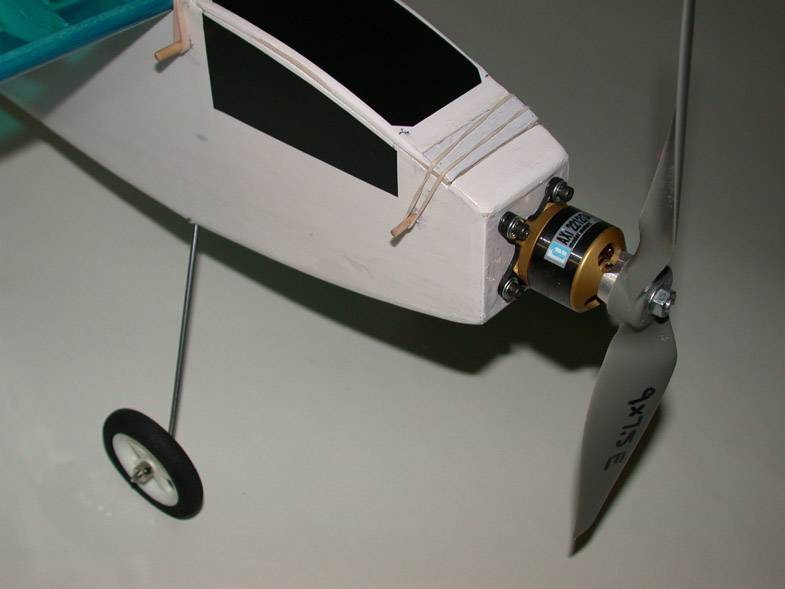
The motor selected was the Hobby Lobby/AXI 2212-34, which can easily produce 100 watts of input power. The motor weighs 2.2 ounces. A Castle Creations Thunderbird-18 amp ESC weighs only 0.6 ounce. A three cell EnerLand 1350 mAh Li-Poly battery pack weighed 3.76 ounces. Using the voltage of three cells the motor current, while swinging an APC 9 X 7E prop, was just under 9 amps.
RC SYSTEM
It was my pleasure to use a prototype of the new Hitech AURORA 2.4 GHz spread spectrum radio system. This included the companion Hitec Optima 7 channel receiver that weighs only around 1/2 ounce. There is only a single short antenna on this receiver so weight and size wise it is perfect even for small size models like this. A total of four Hitec servos were used, two on the ailerons, then one for the rudder and another for the elevator. I also added in flaperon control since I was using separate aileron servos. A detailed review of this entire new system will have already appeared in FLY-RC prior to the publication of this article. The total weight of my power and RC system was something like 8.8 ounces. I generally figure that the structure weight should be about the same. As it turned out the final weight was exactly 16.3 ounces.
FINISHING
The entire structure was covered with BP Hobbies Solite iron-on covering material. The wing and stab were done in transparent blue with the fuselage and fin in opaque white. Decals as always was from Callie Graphics.
WEIGHT and BALANCE
As already mentioned the final weight was 16.3 ounces and that included a small amount of lead weight at the tail. Despite the rather short nose length I ended up slightly nose heavy. An alternative to adding weight might be the substitution of a lighter weight battery pack, like a 900 to 1000 mAh instead of the 1350 that I used. Doing that would reduce the weight and at the same time the added ballast in the rear could be removed for a further weight savings. The wing loading at 16.3 ounces worked out to 11.7 oz/sq.ft, which is quite light!
FLYING
Now comes the fun part – it flew just great! For information the control throws were as follows: elevator 1/4 inch either side of the neutral position, ailerons 1/4 inch either side, rudder 1 inch either side and the flaperons dropped about 1/4 inch when deployed. The PARK-PATTERN was certainly lively at over 100watts/pound. Full power provides vertical climb performance. It takes off a relatively rough grass flying field without difficulty. In fact it literally jumps off the ground. With all that power you can actually do regular maneuvers at half throttle. This helps extend the motor run time considerably. I did add in about 25-30% of expo rate control on both the elevator and ailerons. It tends to smooth out my 71 year old flying skills! To me, being able to do most of the regular RC pattern maneuvers, with a PARK FLYER size aircraft was truly fun!
SUMMARY
I feel like I was able to capture all the features I wanted in this particular design. It builds very fast. In my case in three days time! There is a chance that Aero Craft Ltd, will be making a kit of the PARK-PATTERN. If not a full kit then a short kit with laser cut ribs. The new Hitec AURORA Spread spectrum RC system provided perfectly smooth control at all times. It has an incredible amount of features. In fact that list of features keeps growing. A totally worthwhile project all the way around!
———————————————————————————————————–
SPECIFICATIONS
Model: “PARK-PATTERN” Designed by Bob Aberle September 2009
Type: An electric powered park flyer size RC model aircraft capable of most standard pattern maneuvers
Wingspan: 33 inches
Wing Area: 200 square inches
Length: 26 inches
Weight: 16.3 ounces
Wing Loading 11.7 oz/sq.ft.
GEAR USED:
Hitec RCD AURORA 2.4 GHz spread spectrum system with the OPTIMA 7 channel companion receiver, two Hitec RCD HS-55 micro servos (ailerons), one HS-50 for rudder and one HS-65HB for the elevator.
POWER SYSTEM USED:
AXI 2204/54 brushless outrunner motor, Castle Creations Thunderbird-18 ESC w/BEC, APC 9 X 7.5E prop, EnerLand three cell 1350 mAh Li-Poly battery (3.76 ounces) (battery actual load for this application = 6.5C)
POWER SYSTEM (parameters)
Motor current: 8.84 amps
Voltage: 11.75 volts
Power Input: 104 watts
Power Loading: 102 watts/pound
Flight Time: 10 to 12 minutes (and more) with some motor throttling
MANUFACTURERS (Source) INFORMATION
Aero Craft Ltd (odd size balsa, if required and laser cut parts, primarily the wing ribs)
www.aerocraftrc.com
BP Hobbies (CA medium viscosity cement with companion accelerator and five-minute epoxy cement, EnerLand Li-Poly battery pack, APC prop and Solite covering material)
www.bphobbies.com
Callie Graphics (license number decals)
www.callie-graphics.com
Castle Creations (Thunderbird-18 amp- brushless ESC)
www.castlecreations.com
DuBro Products (micro control horns, micro EZ-Connectors, lightweight wheels and wheel collars,)
www.dubro.com/
Hitec-RCD (Aurora spread spectrum RC system and all servos as listed))
www.hitecrcd.com
Hobby Lobby International (AXI motor)
www.hobby-lobby.com
Stevens Aero Models (.073 Yellow Teflon Tubing for elevator control rod)
www.stevensaero.com/shop/product.php?productid=16639
•
Park Pattern Construction – Sheet 1
•
Park Pattern Construction – Sheet 2
•
Park Pattern Construction – Sheet 3
•
Park Pattern Construction – Sheet 4
•
Park Pattern Construction – Sheet 5
•
Park Pattern Construction – Sheet 6
•
Park Pattern Construction – Sheet 7
•
Park Pattern Construction – Sheet 8
•
Park Pattern Construction – Sheet 9
•
Park Pattern Construction – Sheet 10
•
Park Pattern Construction – Sheet 11
•
Park Pattern Construction – Sheet 12
•
The following series of images is intended to share more construction details of Aberle’s prototype and to compliment the original article. You can click on any image to open a larger version in a new window.
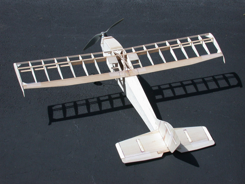
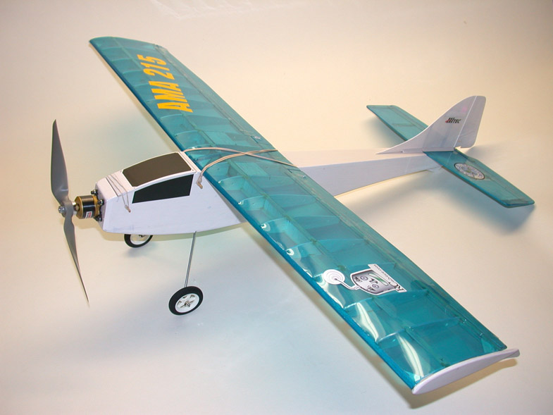 The completed PARK-PATTERN ready to fly at 16.3 ounces total weight and 11.7 oz/sq.ft. wing loading. Plane is a PARK FLYER size that is capable of most of the standard RC pattern maneuvers. |
 PARK-PATTERN is covered with BP Hobbies Solite iron-on covering material. Should wing location makes it easier to hand launch. PARK-PATTERN is covered with BP Hobbies Solite iron-on covering material. Should wing location makes it easier to hand launch. |
 The finished structure prior to covering. Simple and inexpensive to build! |
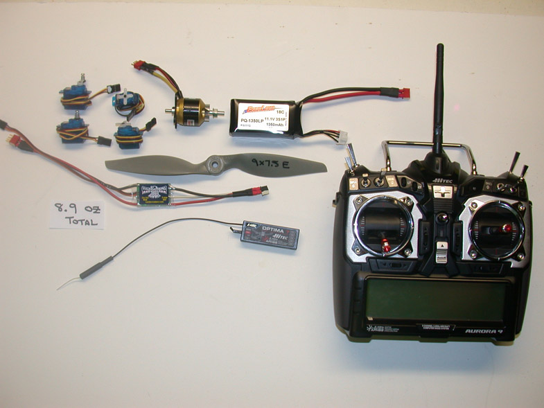 The complete power and RC system that weighs 8.8 ounces. The radio is the new Hitec AURORA 9 channel 2.4 GHz spread spectrum system, including the companion Optima 7 Channel receiver. |
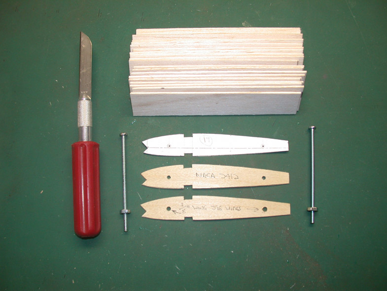 Preparing to cut out a batch of wing ribs using two plywood templates and an X-Acto knife with a long blade. |
 Two long machine screws hold the sandwich of balsa blanks between the two templates as the wing ribs are carved to shape. |
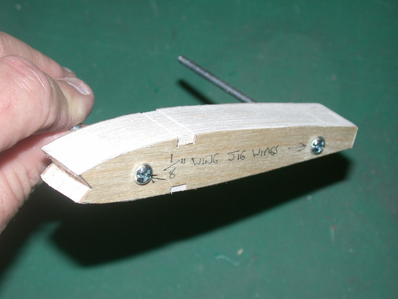 Here the carving is complete and the two machine screws can be removed yielding a perfectly accurate set of wing ribs. |
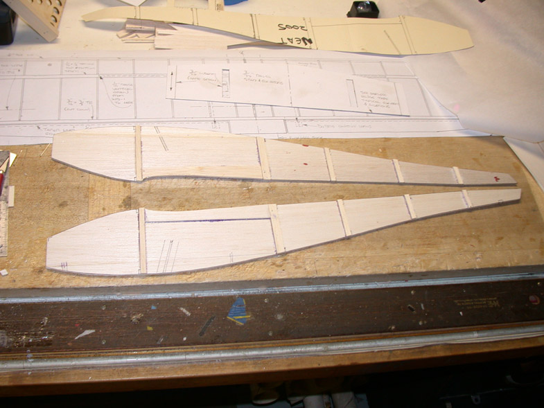
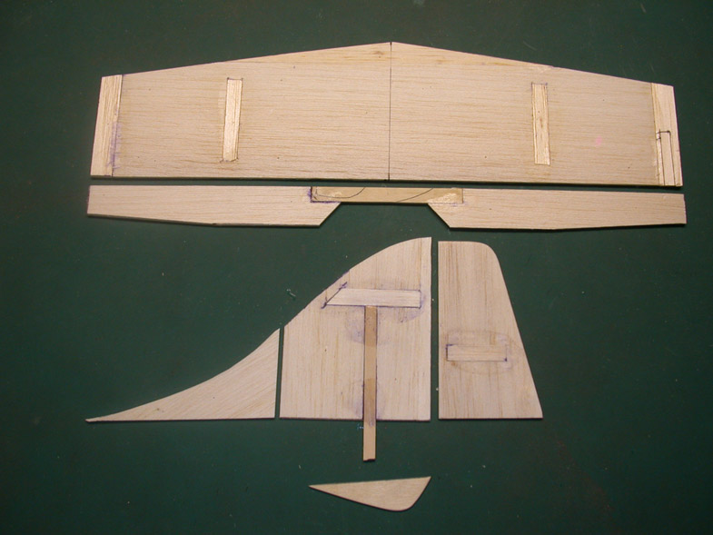
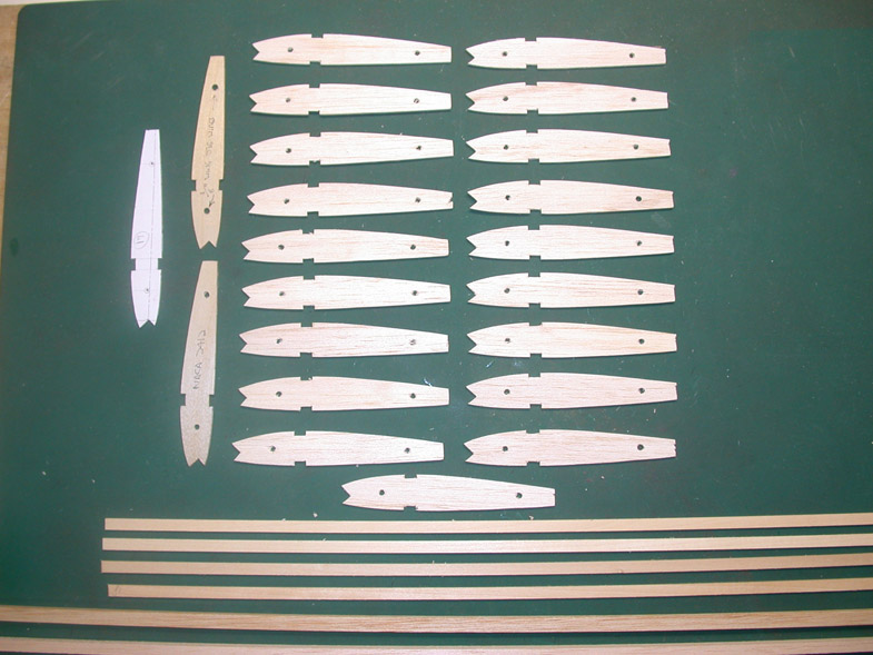 The wing ribs, leading and trailing edges and spars ready for assembly. |
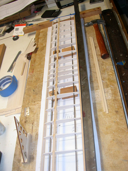 The wig jig wires are raised off the building board with several wood blocks. The ribs are then spaced out over the full size plans. |
 The wing panels are joined with a small amount (1/2 inch) dihedral at each tip. |
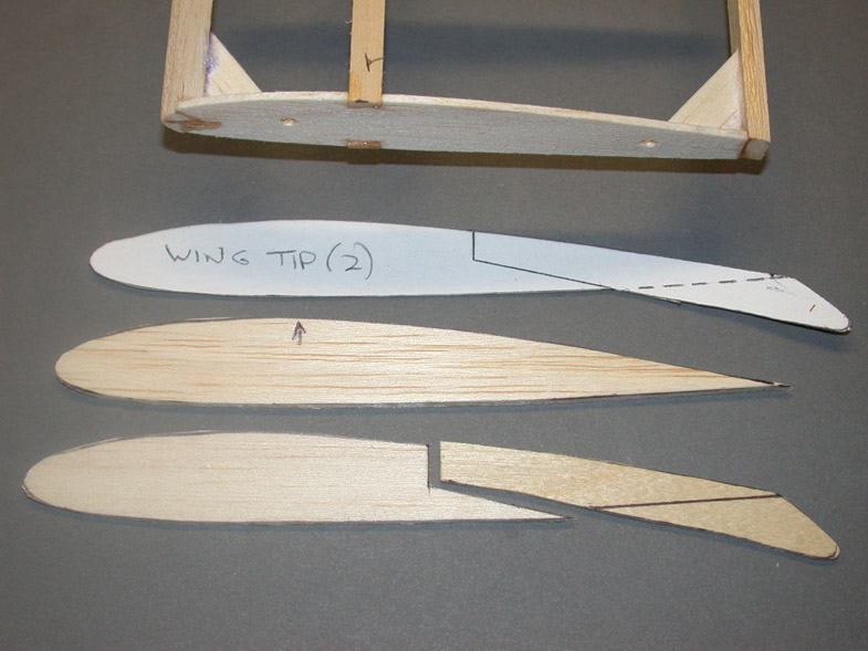 The wing tips are made from balsa along with a 1/16 inch plywood skid that protects the ailerons. |
 The fuselage sides have been cut out and some of the stiffeners have been added prior to joining the sides. |
 Aero Craft Ltd builder’s triangles are used to align the two fuselage sides over the top view of the plans. |
 Bob fashioned a rear fuselage support from scrap balsa wood. This was needed because of the upward slope of the fuselage as it approaches the tail. |
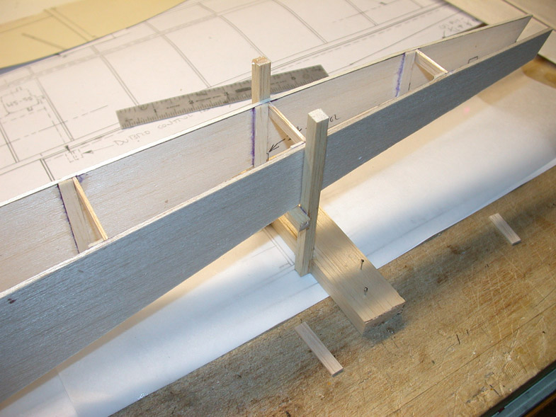 A closer view of that rear fuselage support. |
 Adding the forward balsa doublers in the battery compartment. |
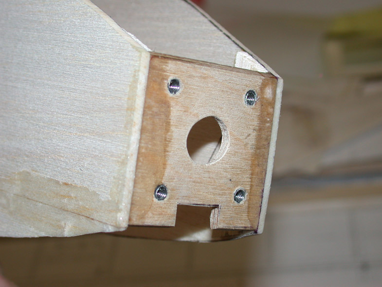 The firewall (F-1) has a center hole to clear the motor shaft and a second slot to clear the cable going back to the ESC. |
 The rear of the fuselage showing that it is open to allow for the passage of the elevator control rod. |
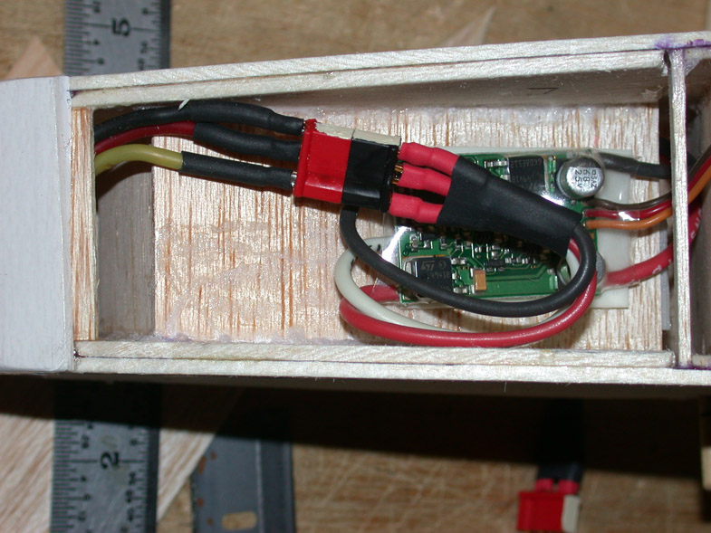
 Looking inside the battery compartment. |
 Another look at the inside of the battery compartment. |
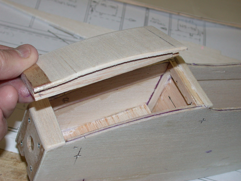
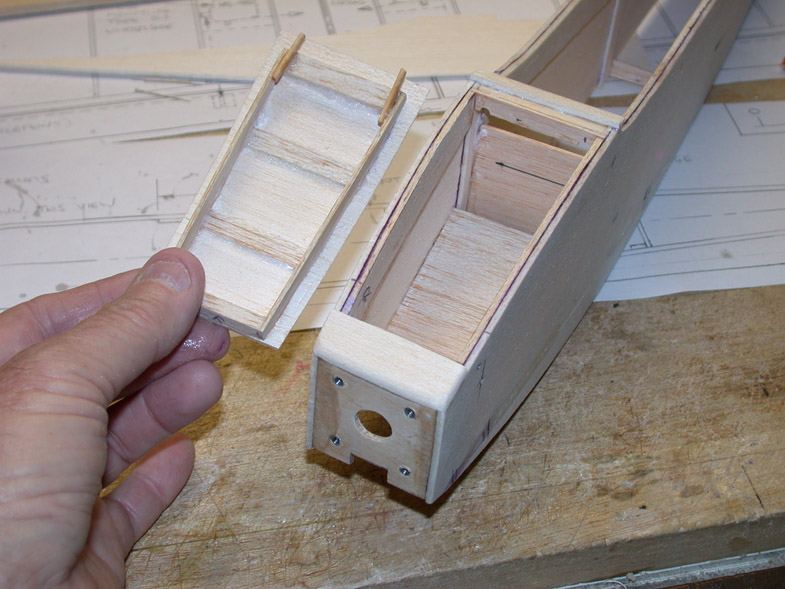 The removable hatch cover. |
 The stab and elevators are made from 3/32 inch balsa while the vertical fin and rudder are made from 1/16 balsa. Note the use of insert stiffeners. |
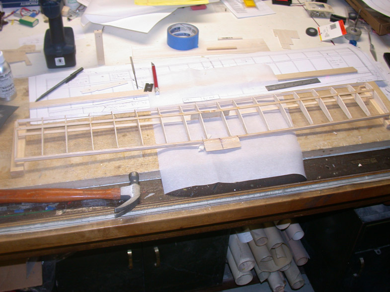
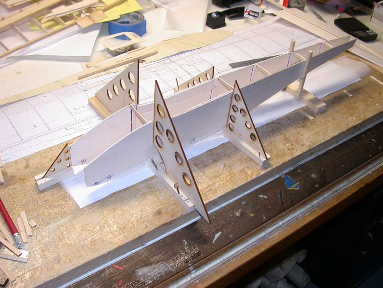
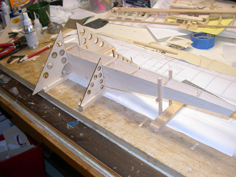
 The completed aircraft frame prior to covering! |
 The elevator hookup at the rear of the fuselage. That’s a DuBro EZ connector. |
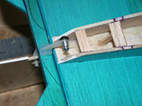
 The rudder control rod attachment point. DuBro mini control horns employed. |
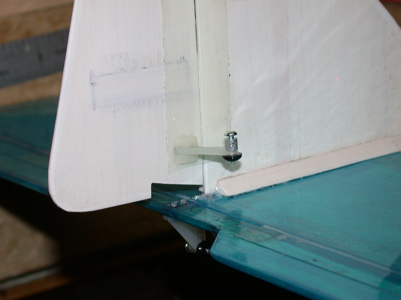
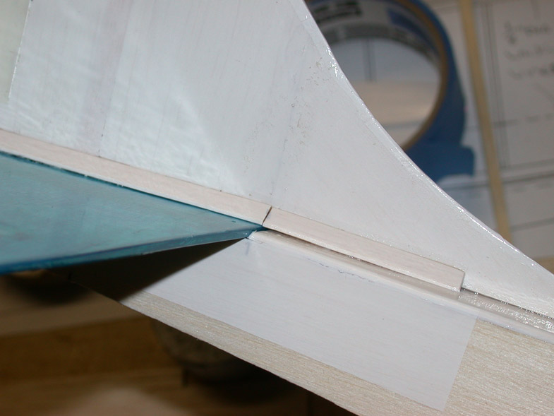 Note the use of 1/4 inch triangular balsa to better support the fin to fuselage joint. |
 The Thunderbird 18 amp ESC is attached to the bottom of the battery compartment. |
 The 3 cell Li-Poly battery is attached with Velcro tape. |
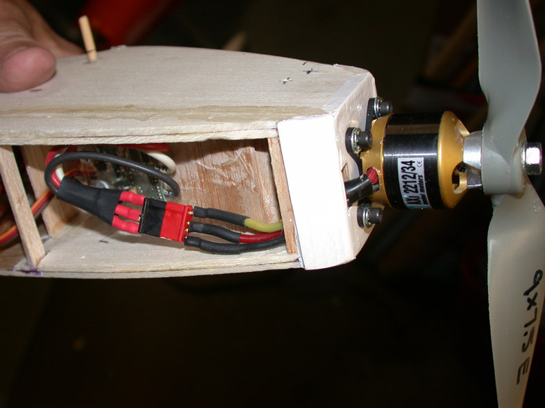 The AXI outrunner motor is mounted to the firewall with four 4-40 hex head screws. |
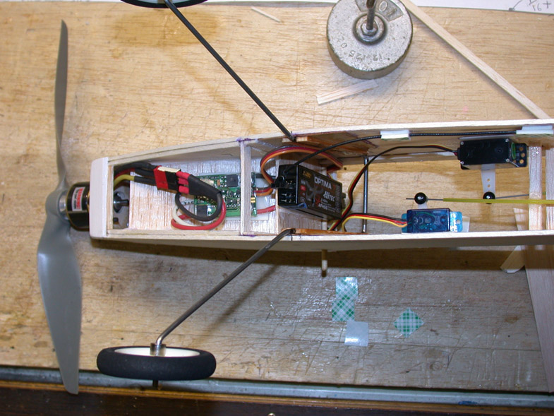 Here you can see the RC receiver and servos before the bottom sheeting is added. |
 The control rod wires are .032 inch diameter and they go inside .073 diameter Teflon tubing from Stevens Aero Models. |
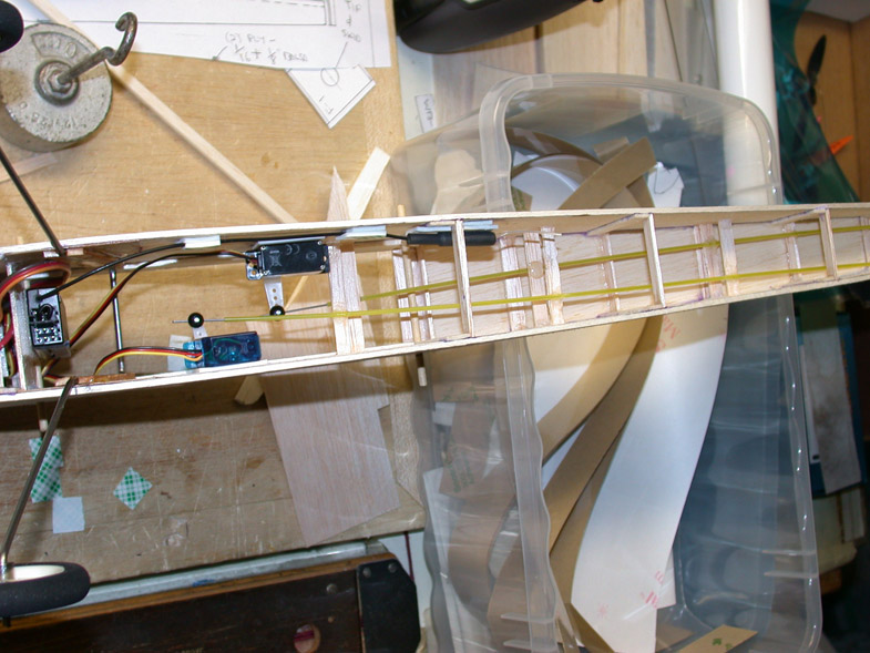
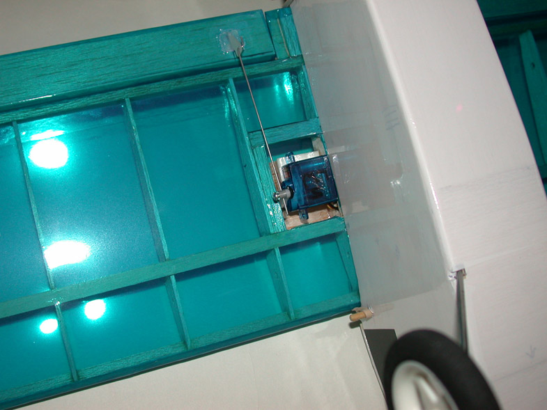 One of the two aileron servos can be seen on the underside of the wing. One servo goes to each aileron. |
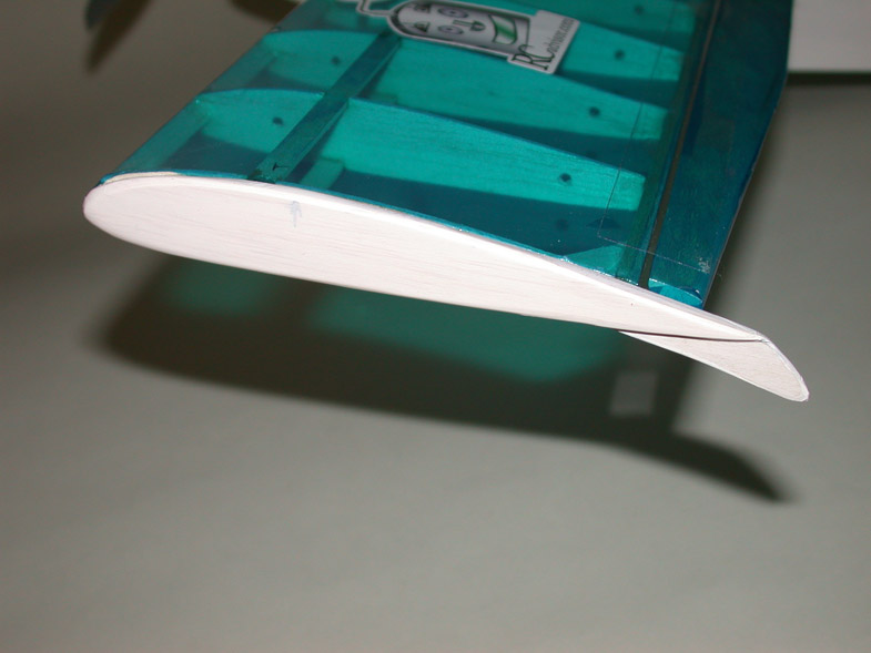 The flat wing tip in place with the plywood skid showing. |
 Flat black vinyl shelving paper was used to simulate the windows. |
 An added touch, Bob used a decal as a tribute to his friend, Carlos Reyes, the RC Advisor. |
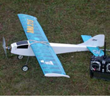 The completed PARK-PATTERN ready for its first flight at the 2009 NEAT Fair. The new Hitec AURORA spread spectrum transmitter stands near the tail. |
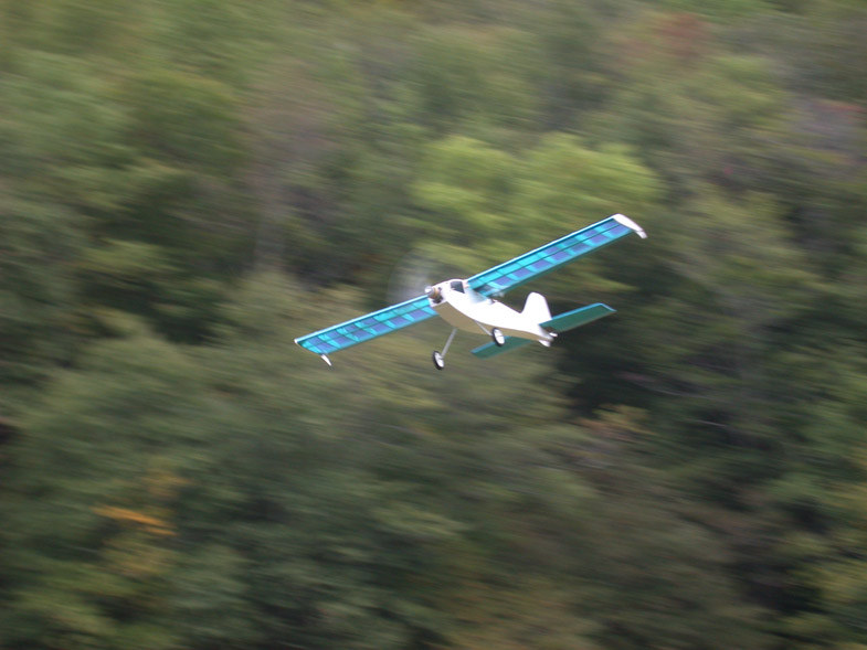 Making a camera pass on the very first flight at the 2009 NEAT Fair. Tom Hunt was on the controls while Bob took this action shot. |
