This month’s column is based on Building the Stinson SR-9, blog No. 20, on www.rcmodel.com. For direct access to all of my blog entries on this (or any other) project, go to the archives tab partway down my home page and click the appropriate subject under categories.
The Stinson SR-9 project is getting very close to the time for me to begin covering and finishing, but there are a few installation details to be completed before I will actually be ready for “closing up” the structure. In the case of this airplane, that means putting on a fabric covering. For me this counts as another seriously fun part of the building process, but it also cuts off access to most of the interior of the airplane structure, so it’s important to have all of the “inside stuff” figured out and in place first. As it turns out, what I’ve got left are a couple of surface panels, the aileron and flap servos and some really unusual extra features you’re going to like. Let’s get with it.
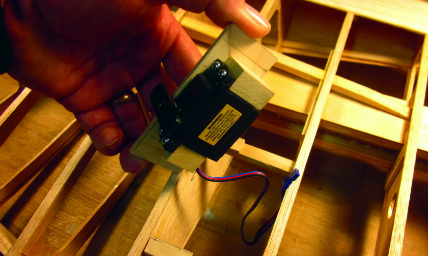
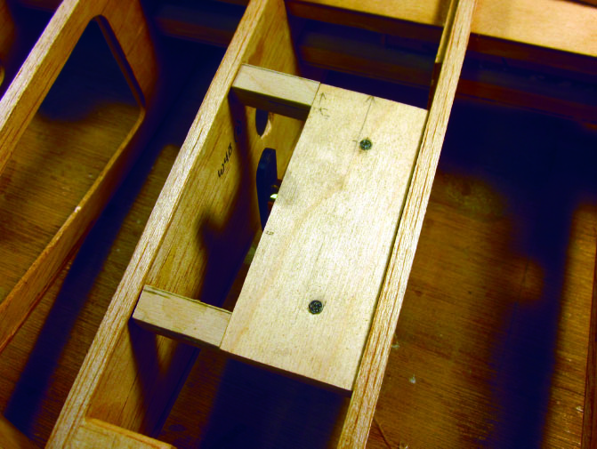
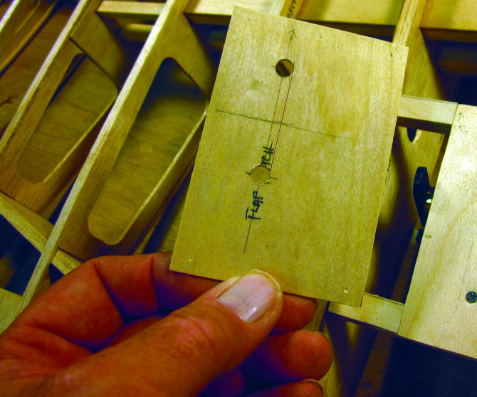
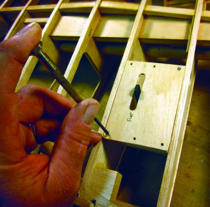
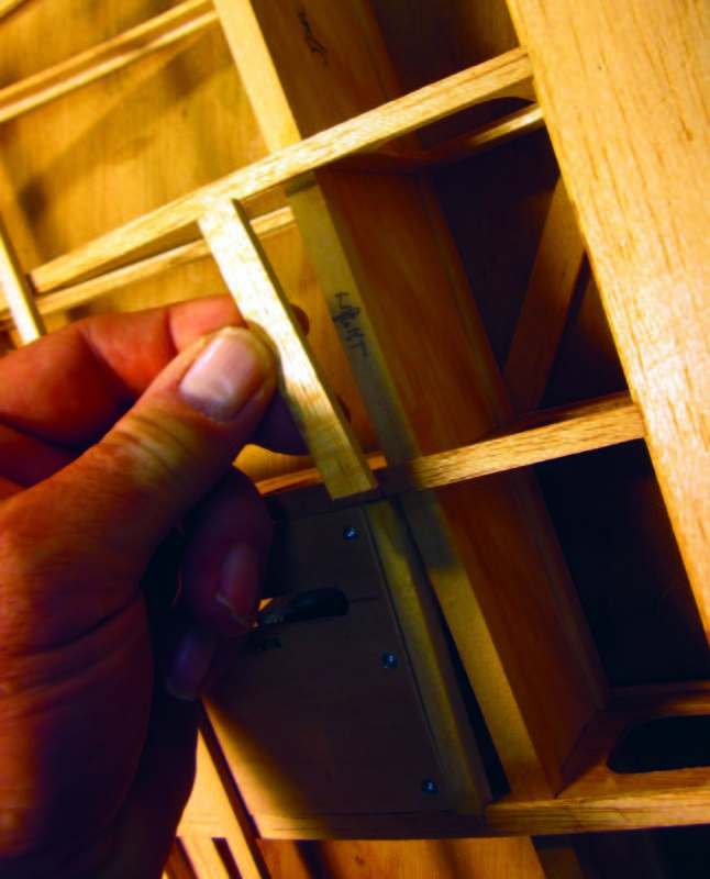
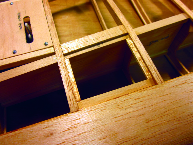
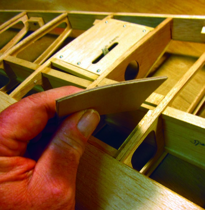
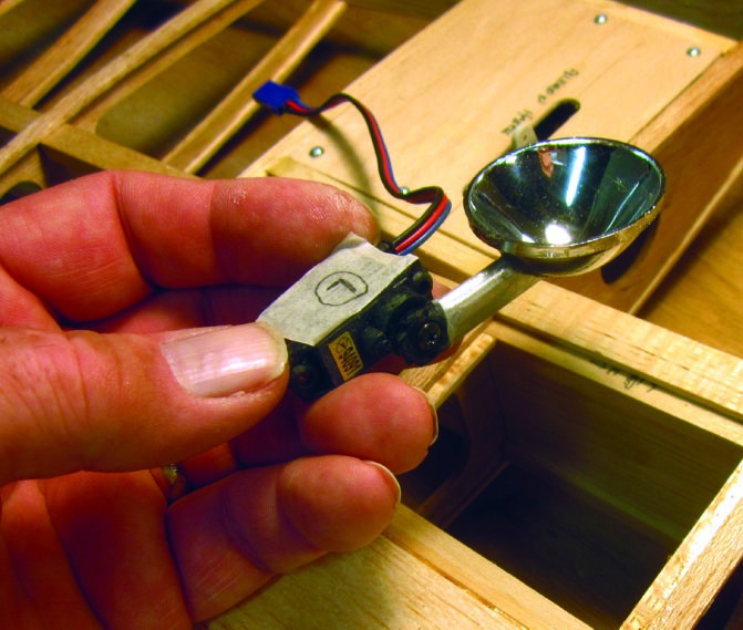
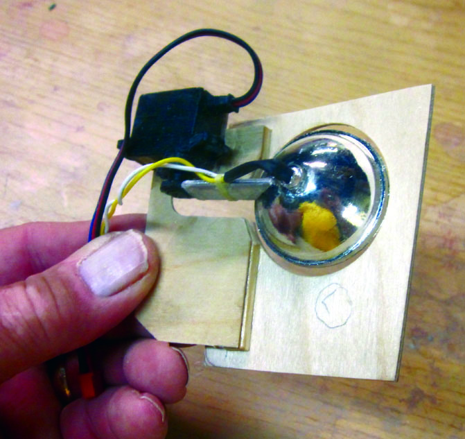
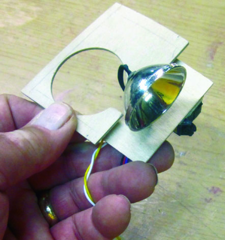
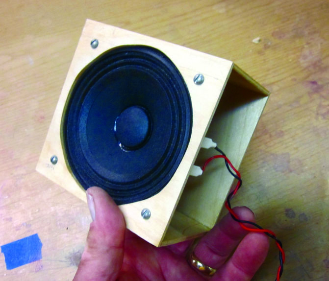
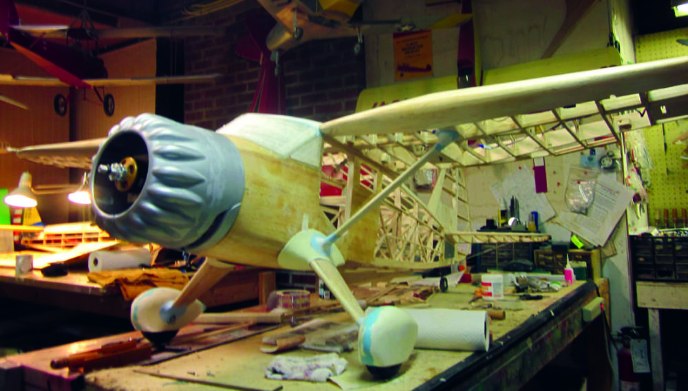
The flap and aileron servos each get their own mounting trays to permit them to be mounted inside the structure (where they belong) and still be removable for maintenance. Here I’m working on the right aileron servo installation. The two 1/4 x 3/8-inch span-wise servo tray supports were put in during the initial wing construction sequence. I have glued-and-screwed a pair of basswood blocks to the servo tray base (exactly per the book) and then mounted the servo to those blocks (again by the book) with standard-issue servo mounting screws.The servo rides inside the wing. Here you are looking at it from the bottom. The servo output arm extends past where the cover plate and fabric covering will be. I’ll cover that big hole shortly. The two screw heads you see are holding the servo mounting blocks to the tray…at this point the servo/tray assembly is resting loose on those two span-wise rails.The kit provides 1/16-inch plywood servo cover plates, which are cut to finished outline shape but not for the servo output arm. This permits you to locate that opening to fit your servos exactly.You can see how neatly the cover plate fits the aileron servo when the opening is custom fitted. The six little flat head wood screws are countersunk into the 1/16-inch plywood plate and hold the entire assembly against those mounting rails. I’ll remove those assemblies prior to starting my fabric work, finish them separately and reinstall them when all the paint is dry.Here comes a feature that doesn’t show up anywhere on the plans. I’m going to add working landing lights (two of them) …but wait…there’s more! The landing lights in the gull-wing Stinsons were not your usual clear-fairing-over-a-light on the wing leading edge deal. These are the funky, ’30s and ’40s vintage retractable lights that swing down out of the bottom surface of the wing to work, then retract when they’re turned off. I worked with one of these, full scale, when I restored my 1946 Cessna 140, and the challenge of making a pair at 1/5-scale for this Stinson was one I couldn’t refuse. What’s happening here is that I’m adding the first of several custom fitted 1/8-inch plywood strips that will locate and define an entirely new removable panel just inboard of each aileron servo bay.I worked back from three-views and full scale reference photos to position and scale the landing light mountings. This is the left wing light mounting base all framed in, along with an extra strip of 1/16-inch balsa sheet to fill between those two ribs, over the spar, to provide a smooth base for the fabric covering.See that gentle curve that shows up along the edge of the plywood? The underside of the wing section (airfoil) is curved at that point and I want the new light mounting plate to match it. What’s my secret? I gave one side of the plywood a generous coat of full-tautening, clear nitrate dope and let it dry overnight. This provides an excellent illustration of why we don’t use tautening dope on most parts of the airplane most of the time…we usually don’t want uneven shrinking and curling.This is one of the retractable light assemblies… basically just a spare mini-servo with the parabolic reflector body from a cheap mini-light attached to a servo arm extension made from streamlined aluminum tubing cut to the right length.Here’s a better look. This is the inside of the assembly. I found several cheap mini lights with a diameter that matched the scale landing light housing and took them apart for their parabolic reflectors. The servo is attached to the plywood mounting plate with double-sided tape for flexibility in case I need it. I have glued a short length of 3/8-inch streamlined aluminum tubing to the reflector body and then fitted the other end to the suitably trimmed servo arm. The two-wire lead from the light housing goes to the white LED from my lazertoyz.com lighting set (thanks, Dan and Diane). This is independent of the servo cable.Look carefully… this is the same unit seen from outside with the light housing extended. Now you can see both light assemblies more or less complete (all they need now are finishing and a couple of mounting screws at the rear edge of each, along with clear lens covers). They are in the retracted configuration. The angle at the rear edges matches the taper in the wing panel structure. The extended flanges, by which I’m hold There’s even more to this tale. I’m installing a working sound generator system to simulate full scale radial engine noise in sequence with the throttle/ ESC function of my Airtronics SD-10G radio. This is one of the two four-inch speakers installed in its custom-built 1/8-inch plywood sounding box, ready to go into the nose of the airplane where the fuel tank might otherwise have been located.
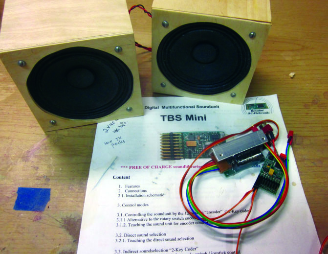
The whole deal. This is a Benedini TBS mini sound system (produced in Germany). What you see here is both speakers, the computer sound generator module, and the speaker amplifier. This will operate from an independent LiPo pack. I’ve already determined that there’s going to be no weight penalty… my primary LiPo power supply from Venom Group is so light that I’m going to require supplemental nose weight, no matter where it comes from, so I’ll let the sound system fill that need for me while it adds class to the airplane’s act.She looks just as good from the other side. Next time we’ll get started working with the Stits PolyFiber covering and finishing products that will turn this framework into a real flying machine.
 Fly RC Magazine WE LIVE RC