This is another of those places where it all starts to get really interesting. The basic structure of the airplane is complete, and that goes a long way toward defining just what sort of model airplane it’s going to be. If we haven’t built in plenty of accuracy, strength and lightness by now, it’s never going to happen. However, jobs like fitting doors (which we did in the last column), finishing a cowl and things like landing gear fairings, struts, etc., take model airplane building to the next level. From now on everything we do is going to show, whether we like it or not.
The focus of my attention this time will be the engine cowl. This is going to be a big deal no matter what, since this airplane, like all Stinson SR (Reliant) models, features a big round radial cowl loaded with detail in the form of eighteen rocker box cover blisters along with exhausts, access panel and various fastenings that we may or may not want to replicate. The basic cowl is supplied as two sections; a front “bowl” and an extended cylindrical rear base. The rocker blisters, or covers, are all pre-molded plastic ready to be trimmed out of their matrix sheets. As is often the case with simple-looking molded components, there is a lot of work waiting in between taking those parts out of the box and having them function as part of a professional looking job of model building.
On this model, that part of the job gets even more demanding. As designed, the kit’s cowl is intended to enclose and hide an engine while making provisions for cylinder head clearances, exhaust openings, needle valve/choke access and so on. Once the engine is installed and adjusted, the cowl comes off only for maintenance and repair. This Stinson is different, though. As an electric model, it makes none of these demands for non-scale openings in the cowl. The issue of battery access must be addressed however, and since it was clear from the beginning that wing removal for battery charging was out of the question, I had to modify the design with a practical, non obtrusive battery access. Simply removing the cowl would have required pulling the propeller and managing a lot of small screws every time I wanted to charge the LiPo pack. For me, that would have seemed awkward and clumsy and I didn’t want to do it. Since the cowl on the full-scale airplane is split into equal halves down the centerline, I used that feature to define my modifications. The left half of the cowl is fixed to a base mounting ring made of plywood that bolts to the firewall. The right half is held to the left with several plug-intube locating pins and four pairs of small rare earth magnets. It slips off easily for access to my LiPo packs and then snaps quickly and securely back into place for flight. Let’s go build it.
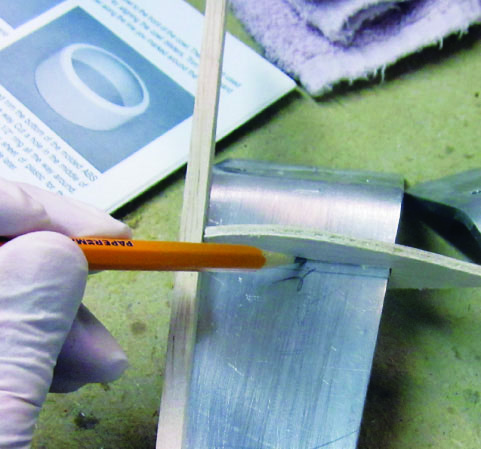
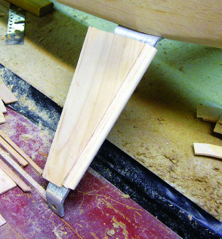
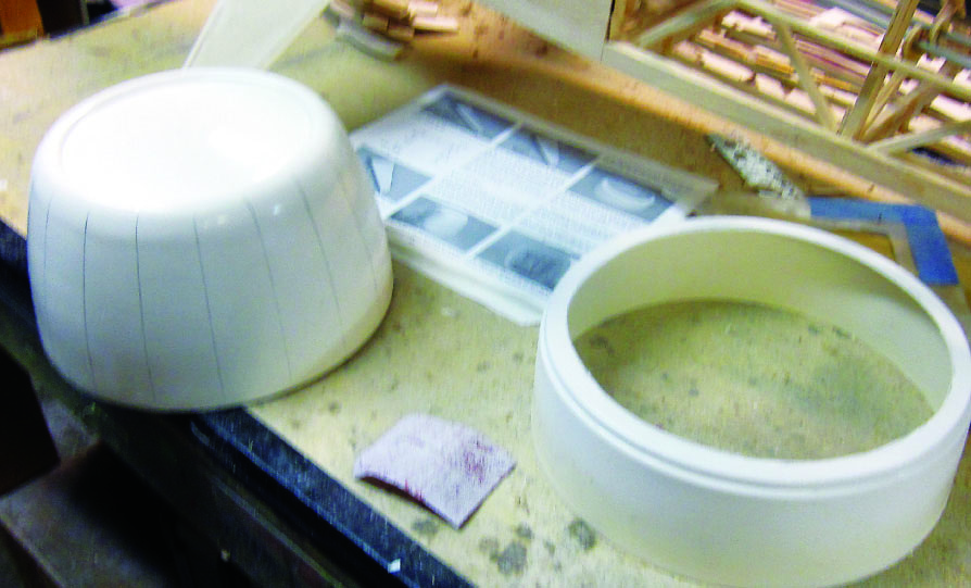
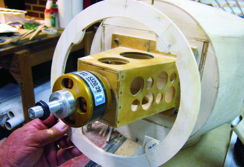
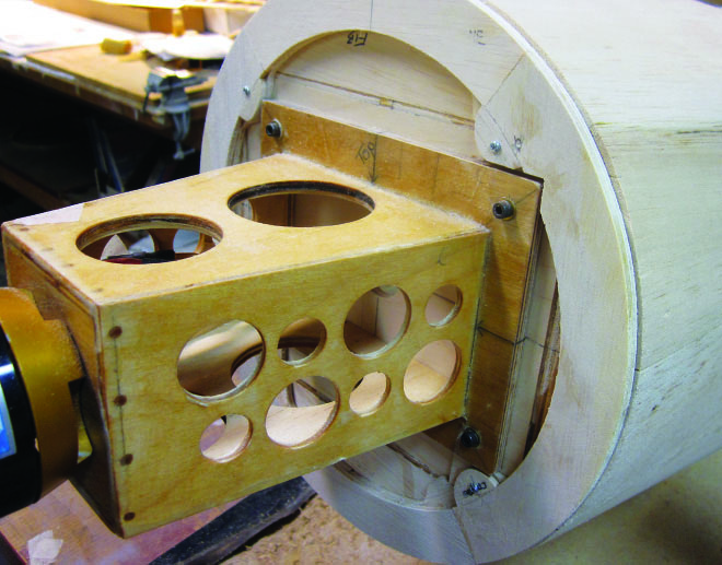
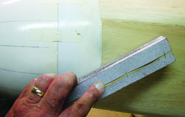
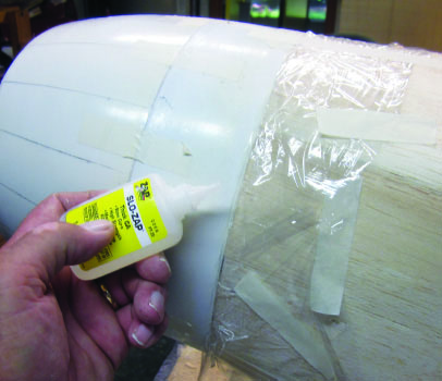
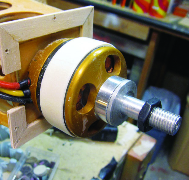
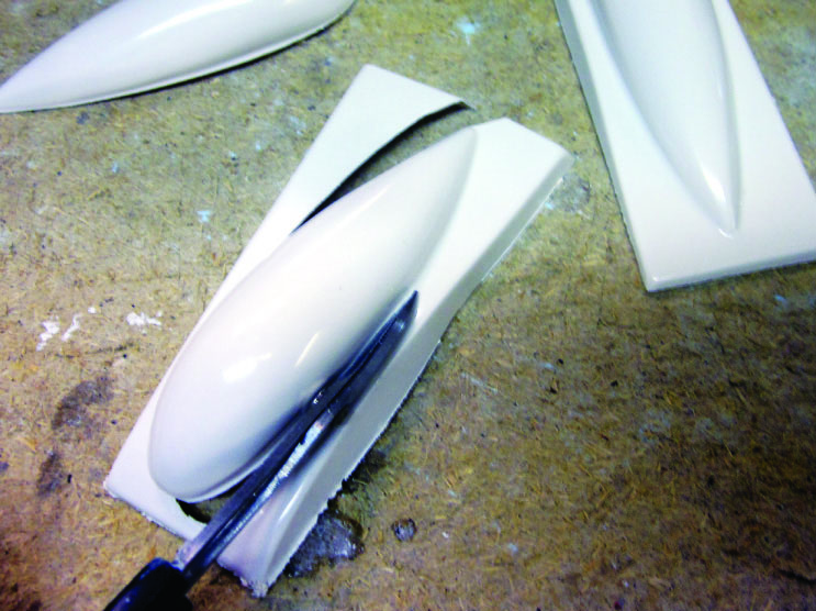
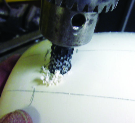
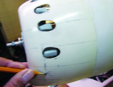
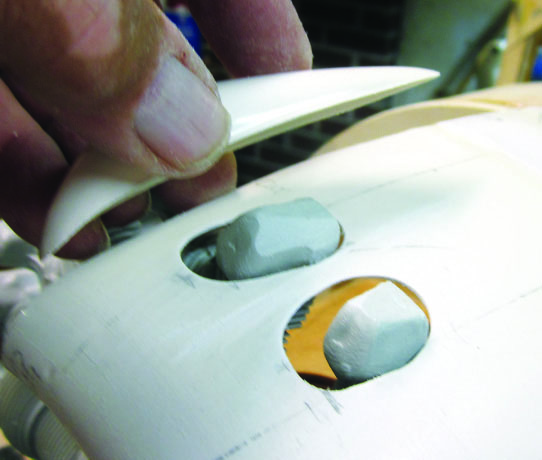
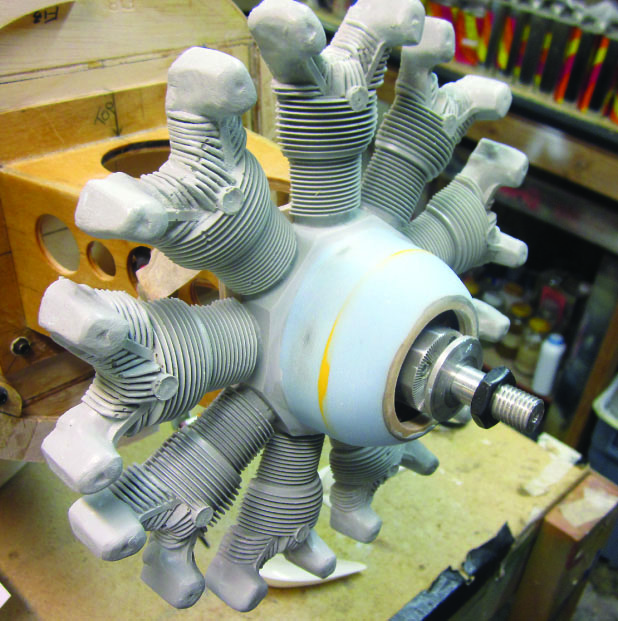
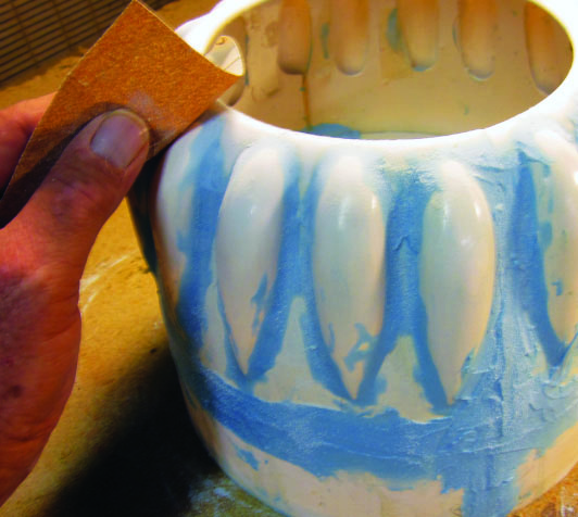
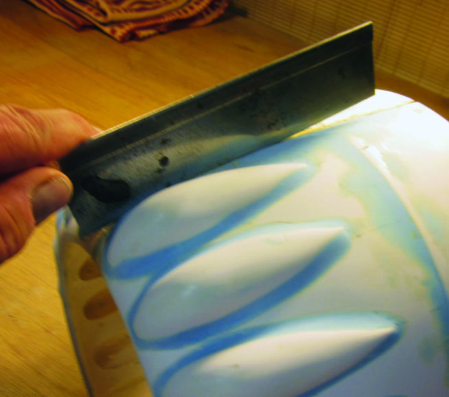
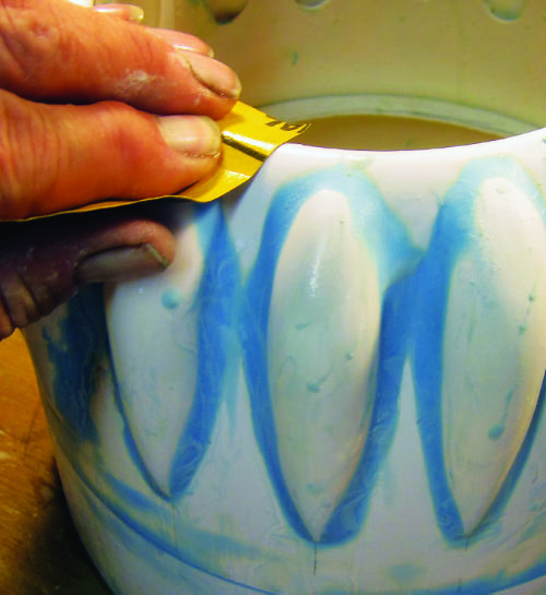
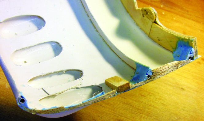
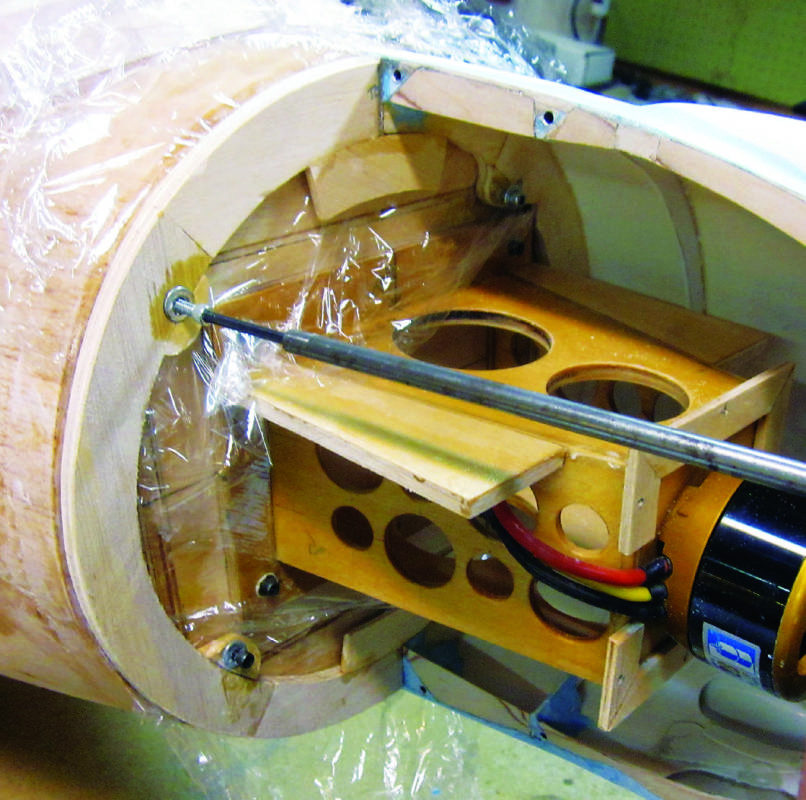
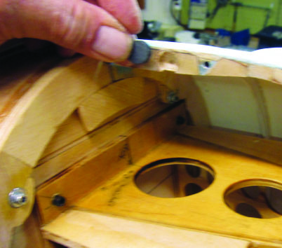
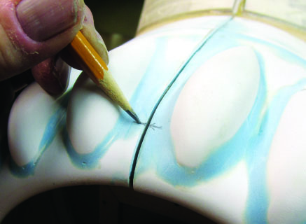
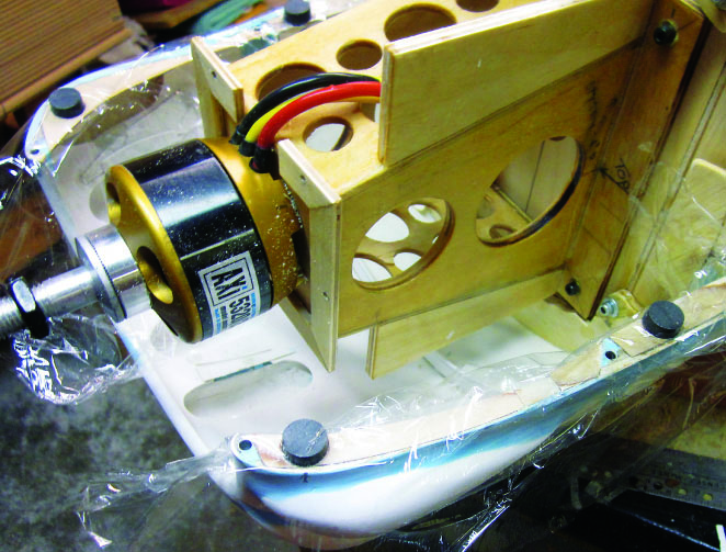
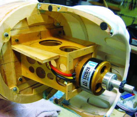
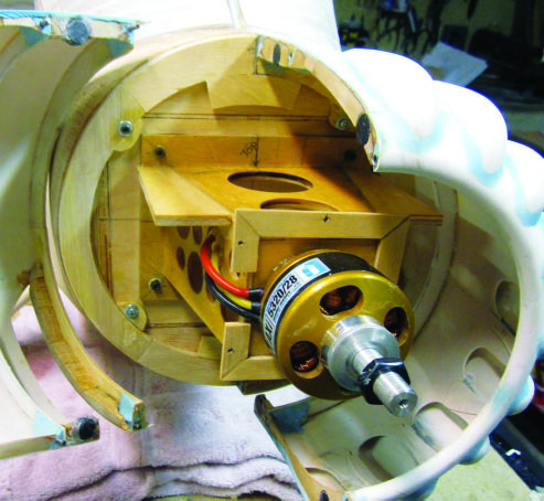
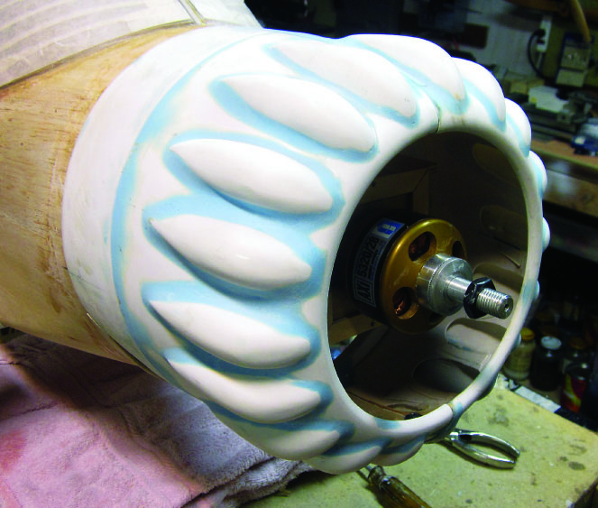
First, I have some catching up to do. A while back I bolted the aluminumalloy landing gear legs in place. Following that, the instructions call for adding the landing gear fairing structure which consists of three die-cut plywood formers on each side and a wrap-around covering of 1/64-inch plywood. Here, I’m marking the exact location of former LG- 1 on the left strut prior to using 30-minute epoxy to fix it in place.This is a front view of the right strut. You can see where I epoxied a strip of 1/4 x ½-inch basswood along the leading edge and sanded it to blend with the rest of the surface.Now we can get started on the cowl. The nose bowl and extension section have both been cut from the molded plastic matrix sheets and then trimmed and sanded to fit neatly together. I left the front section of the nose bowl uncut for now. More on that soon!I built up the cowl ring from the various die-cut plywood forward and aft cowl ring sections. Here, I’m slipping it back over the motor and mounting box to rest against the fuselage front/firewall.Here’s where the results of careful fitting pay off. The cowl mounting base fits snugly around the motor box with its mounting tabs aligned to bolt it independently to the firewall. Notice that the outer circumference fits with an offset just equal to the thickness of the cowl.After letting the ZAP cure, I used a coarse sanding block (80 grit production paper) to smooth off the outer contour of the joint between the cowl and the nose. Since I made sure the ZAP formed a shallow lip around the rear circumference of the cowl, this finished joint creates a precise fit that permits me to remove the cowl and easily slip it back into the right position if I need to.In spite of all my efforts, the fit of the 1/8 inch, balsa-sheet nose skins to the rear edge of the cowl wasn’t perfect. I sanded away the high spots, slipped the assembled cowl into place with a sheet of plastic wrap inside to protect the nose sheeting, and used slow (thick) ZAP CA glue along the rear edge of the cowl to create an accurate and secure mounting base.For the next step, I pulled the cowl off and set it aside to work on the dummy engine and its mount. As you’ll see, since that part of the assembly determines exactly where the rocker box blisters will go, the dummy engine has to be located before we can go any further. I’m going to use a 1/5-scale, generic, 9-cylinder, radial engine resin casting from Frank Tiano Enterprises. The relationship of the full-scale engine to the cowl determines exactly how far fore and aft the model engine needs to be mounted. With that figured out, I adjusted the dimensions of the 1/5-scale crankcase so it would fit the cowl and the AXI 5320 motor, then I worked out where the rear face of the dummy would need to be for all that to work. This determined the exact position of the “picture frame” mount around the rear end of the motor. The inside of the dummy engine crankcase is opened up for about 1/8-inch of clearance around the AXI motor. This 1/8-inch thick wrap of masking tape ensures that one centers directly on the other.The rocker box blisters are supplied as individual moldings, each within its own matrix sheet. All eighteen must be trimmed to shape, one at a time.Now for the messy part; the molded cowl must be cut out to fit over each of the eighteen dummy rocker box covers (unless I want to cut back the dummy cylinder heads inside and compromise the appearance of the finished airplane). Since this is not an exact scale model and I have no precise drawings to work from, it made the most sense to pencil mark the cutout locations one at a time, cut them out with a rotary burr on the drill press, and then go back and adjust and correct one at a time until I got them all right.Take your time, cut cautiously, and when you’re done it ought to look like this.The rocker box blisters go on like this. You’ll need to do some careful trimming and sanding to get a close fit, but there’s no other way I know of to get it right. Right: The as-yet-unfinished dummy radial in position over the tape spacer.No matter how carefully you fit those blister moldings, there will be little gaps and crevices everywhere, and there’s supposed to be a wide radius fillet around the base of each one. I used Stits SuperFil twopart epoxy putty (the blue stuff) to build up the required fillets. Here I’m beginning the job of sanding it out using 100-grit production paper (dry) so I can see exactly how the abrasive is cutting.You don’t need me to tell you that sanding epoxy putty dry creates lots of dust. I switched over to 220-grit wet-or-dry with lots of water to finish the job. There is no way you can rush this part; it’s going to take at least a couple of hours, but the results of getting it right are worth it.While the cowl was back on the airplane, I very carefully marked a centerline along the top and bottom. This is where the cowl splits apart on the full-scale Stinson. A sharp razor saw keeps the job of cutting the two halves apart under control.What you didn’t get to see before was my putting those little corner fillets of SuperFil into six spots on the top and bottom along the centerline inside the cowl. Inside each fillet is a carefully positioned length of 1/8-inch I.D. aluminum tube at right angles to the plane on which the cowl splits. When I made the cut, the open end of each half-section of tube appeared in exact orientation to its opposite half. I’ll add steel wire locating pins to each pair of holes to ensure alignment of the completed cowl.
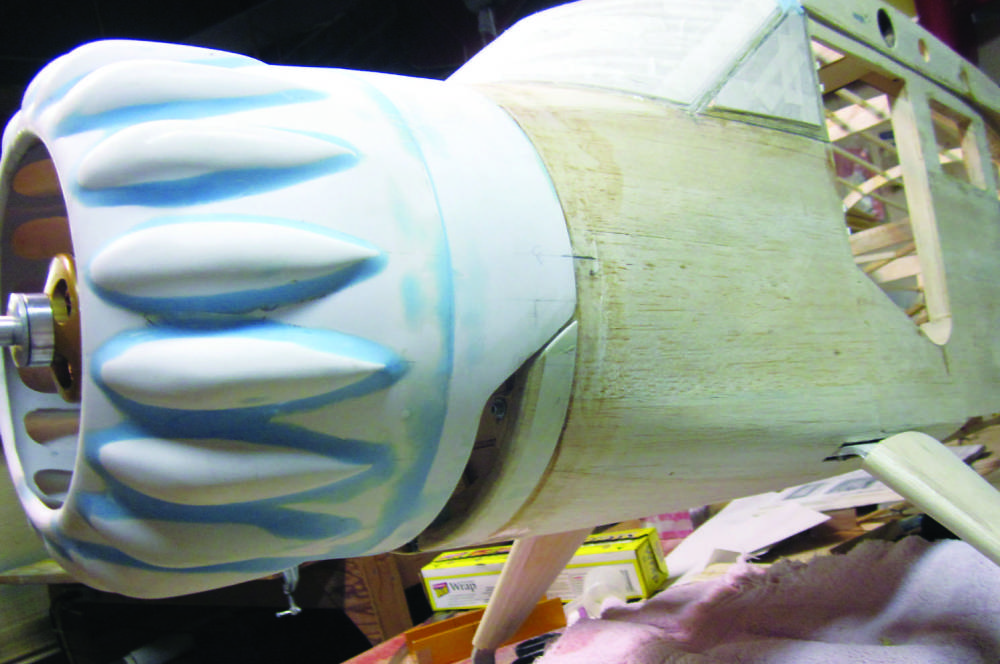
During the initial assembly, I left the cowl mounting ring attached to what would become the left half. When I cut the cowl in half, I split the left and right halves of the mounting ring, too. Now I’ve bolted the left ring with its attached cowl section back into place on the firewall, then added the right half of the mounting ring without the cowl half. I’m gluing them together with a couple of semi-circular 1/8-inch plywood reinforcements. The plastic wrap behind the mounting ring will keep the adhesive where I want it after I snug up all four cowl ring mounting bolts.Here’s the fully-sanded cowl fitted in place on the airplane. Note: I worked on the windshield while you weren’t here. I’ll devote a whole installment to that part of the job soon.I added a flange of 1/16-inch plywood along the inside of each of the parting edges and backed up several points on each one with little blocks of ¼-inch thick balsa. I then cut three shallow, ½-inch diameter holes through the top and bottom plywood flanges into the blocks and fitted a ½-inch rare earth magnet into each hole so the outer surface of each magnet will lie flush with the plywood.With the right half of the cowl slipped back into place, I marked the location for each of its magnets.Prior to taking this shot, I cut oversized holes for each of the magnets in the right cowl half to allow space for each to move as needed to mate up exactly with their opposites. I’ve turned the entire fuselage onto its side to create a level working plane for the next part of the job so the wet epoxy will stay where I want it. With more plastic wrap in place to keep the epoxy under control, I dropped the right side magnets into place, letting them sort out their polarity and get centered.
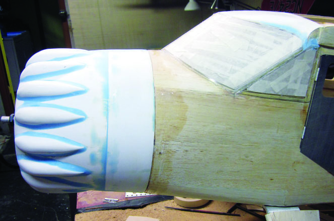
I seated each of the magnets in the left half of the cowl into epoxy and let it cure hard.When I fit the right cowl half into place, lining up each of the guide pins into its respective guide tube and ensuring that each new magnet seated properly in its hole, I snugged both halves tightly into place with masking tape and left it overnight to cure. When I opened it up the next morning and cleaned up the plastic wrap and epoxy “squeezeout”, this is what I had.Here’s the finished cowl all ready for priming and sanding prior to painting. Later on, I’ll demonstrate how easily I can remove and replace it to install battery packs and so on.Sometimes I just have to go off on my own and work without an audience. This is the scale cooling air exit I built per fullscale SR9 drawings and photos. I’ll give you a better look at this later on as well.
That’s all we have room for here, but there’s more. Go to http://www.rcmodel.com/2013/01/building-the-stinsonsr-9-16/ to see all the rest of the details of Stinson blog No. 16.
 Fly RC Magazine WE LIVE RC