This month’s column is based on Building the Stinson SR-9, blog No. 19, on www. rcmodel.com. For direct access to all of my blog entries on this (or any other) project, go to the archives tab partway down my home page and click the appropriate subject under categories.
The Stinson SR-9, like most high-wing, single-engine monoplanes of the 1930?s, relies on external strut bracing to stay together in flight. The SR-9 uses a single, large strut under each wing rather than the multi-strut assemblies like the ones you’re familiar with on Pipers, Aeroncas, Taylorcrafts, and so on, and it uses a pair of rigid horizontal stabilizer struts rather than the set of four tail brace wires common on those smaller airplanes. Top Flite’s designers created this SR-9 to be structurally independent of load-bearing struts, so you could fly the model without them…but that would spoil the appearance. (They do suggest that if you intend to perform any sort of aggressive aerobatics with your model you modify the wing struts to make them load-bearing.) Nonetheless, even if your wing and tail struts are there just for show, they have to look right and support themselves under normal flight loads. I’m going to make up both pairs for this SR-9 to that set of standards.
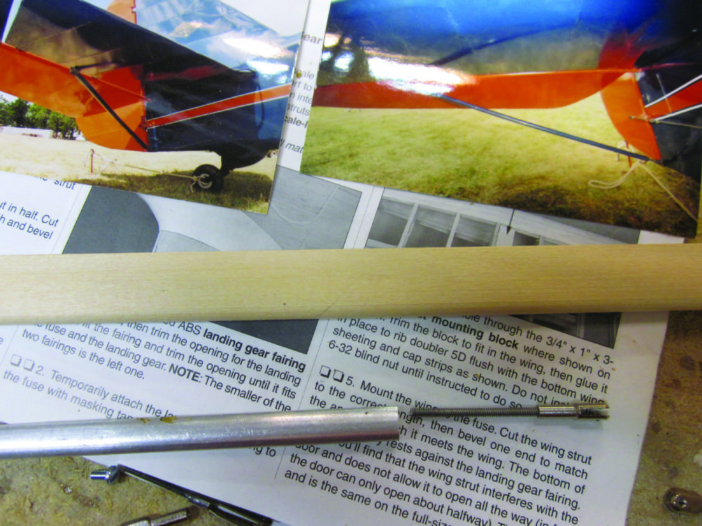
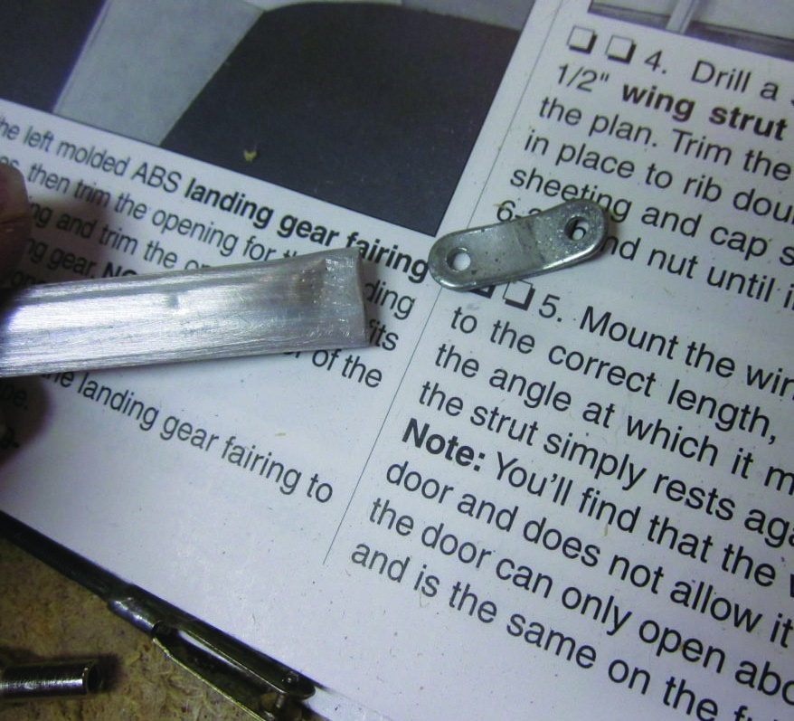
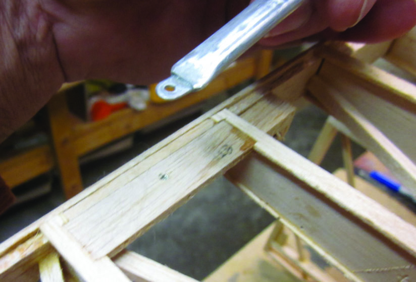
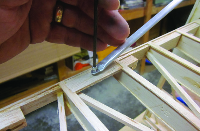
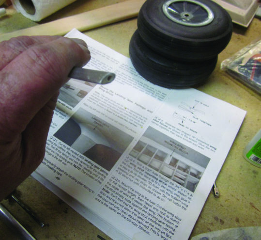
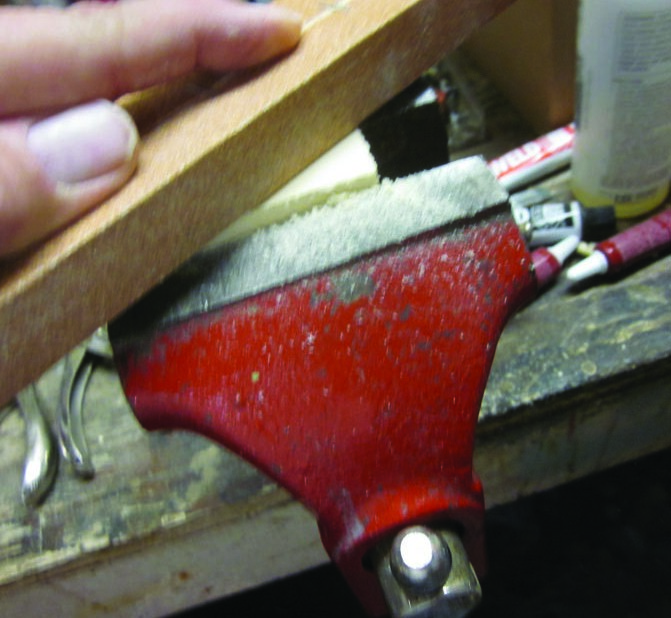
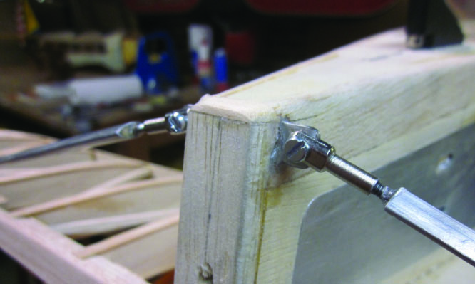
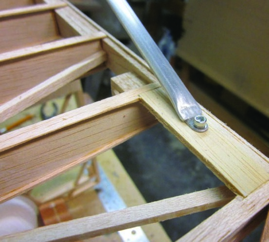
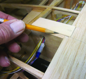
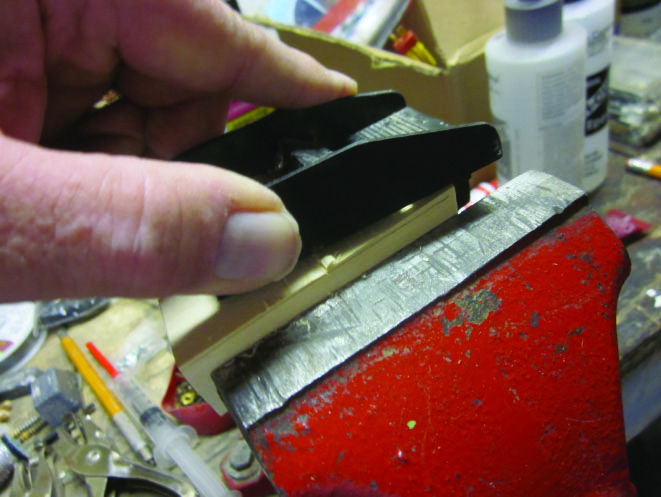
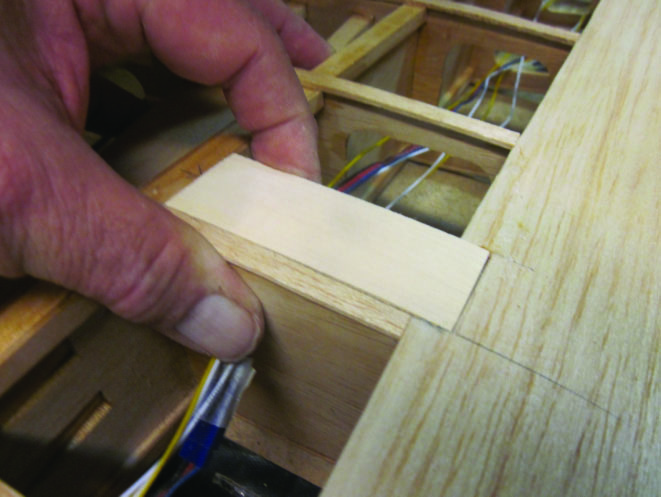
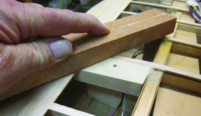
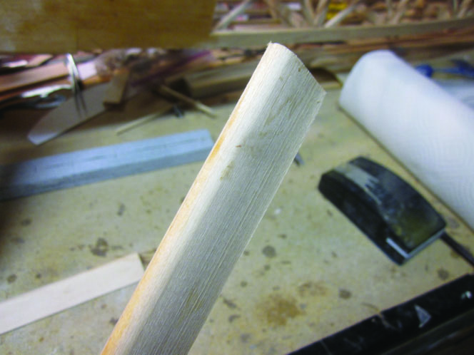
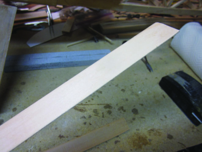
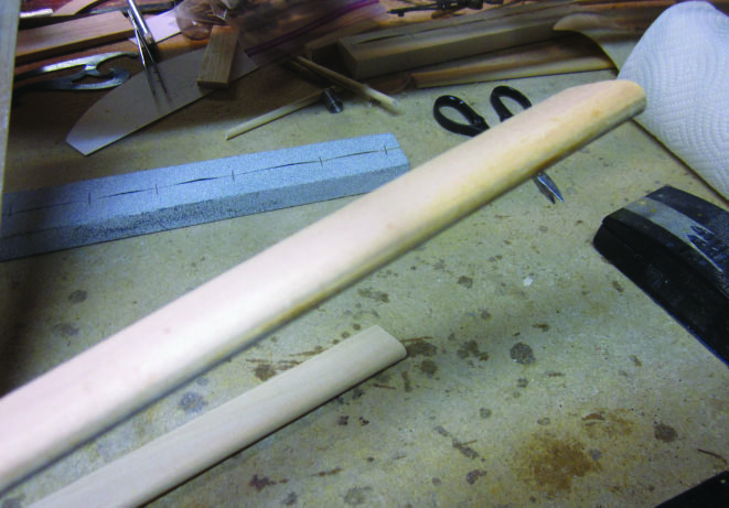
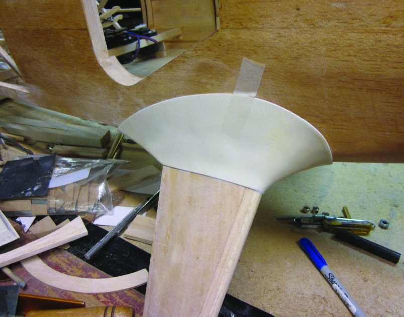
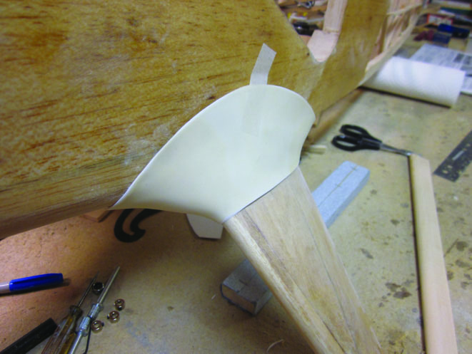
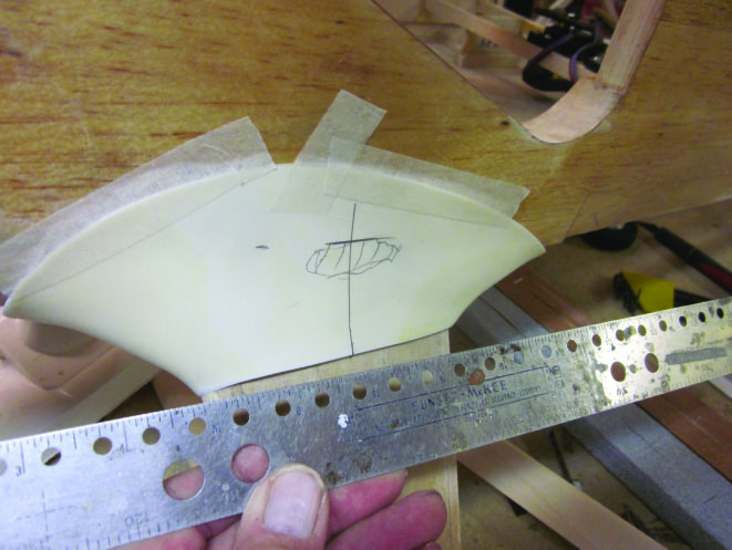
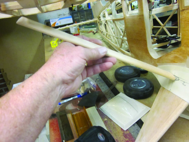
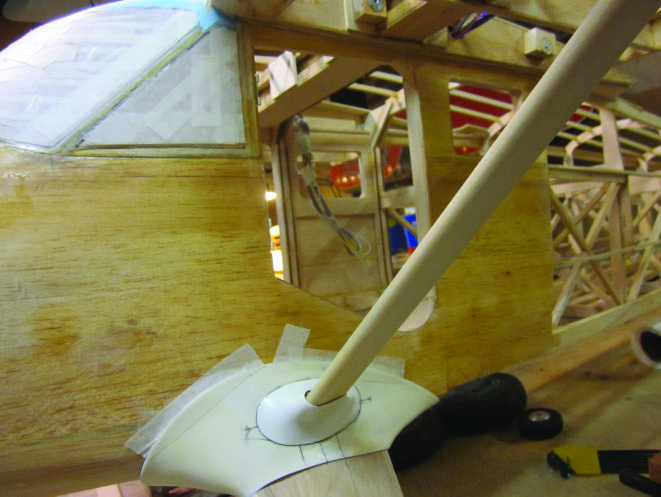
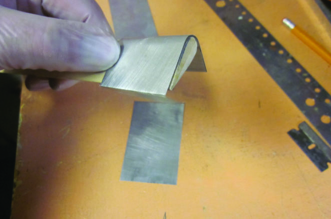
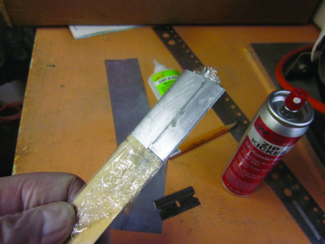
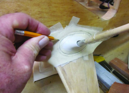
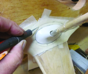
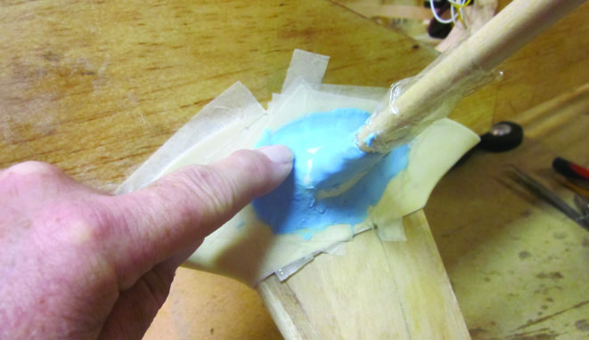
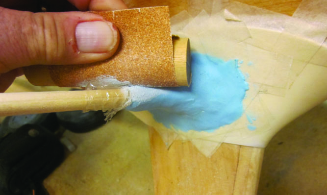
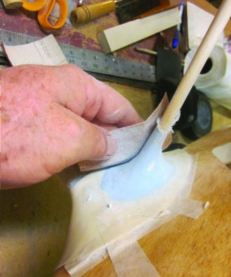
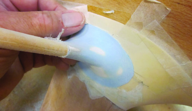
Let’s start with the tail. Right away I encountered a problem to solve and an opportunity to make my model look better (closer to scale). The horizontal stabilizer strut material provided in the kit is WAY too wide and thick. Compare the airfoil sectioned length of basswood from the box with the tail strut shown in the two reference photos of a full scale SR-9. The model wouldn’t care if I used that chunk of wood, but you and I would sure notice it and wonder why it looked wrong. I dug around in my stash of old leftover stock and found enough 7/16-inch K&S streamlined aluminum tube to do the job. A close look at those photos shows a rod end fitting at the fuselage end of the full scale strut, so I cut a short length of 4-40 threaded rod and fitted it to a DU-BRO 4-40 rod end.The flying surface end of each strut uses a flat metal tab that will bolt to a metal strut fitting attached to the stabilizer trailing edge. I made mine from a piece of the flat metal tab supplied with the DU-BRO rod ends.I pressed the end of the aluminum strut flat against the pre-bent tab, smoothed the corners with a file and locked the tab in place with a generous shot of ZAP-A-GAP up the end of the strut. That’s going to work OK “just for show”, but if this were a working strut I would reinforce the end of the tube and put a bolt through the joint for strength. I added the basswood strut mounting block per the kit instructions. There’s a 4-40 blind nut on the other side of that hole I drilled in it.A ½-inch 4-40 screw will complete this end of the strut assembly. The other end is still “floating free” at this point.I’m going to use that stock 4-40 rod end at this end of the strut. Here I have packed the end of the aluminum tube about ¾-inch deep with scrap basswood,flooded it with thin CA, and then drilled and tapped the end for that 4-40 threaded rod.Here, I’m using 80-grit production paper on a long block to bring what will be the lower/outer surface of the strut mounting block into line with the guide marks I made.Assembled, that looks like this. What I didn’t show you separately was the extra piece of flat steel tab I cut to fit through the tail post at the end of the bottom longeron to protrude out each side far enough to accept the rod ends and their retaining screws.Here’s the other end of the strut with that Allen head 4-40 screw in place. I’ll disassemble all of this prior to covering the airplane and then open the screw hole through the fabric and install the painted strut during final assembly.Now we get to the wing struts. The kit provides a pair of pre-cut basswood blocks to assemble into the wing structure between the main and leading edge spars and against one rib as a mounting base for the outer end of the strut. Here I have it dryfitted in place so I can use a pencil to mark where it needs to be trimmed to fit flush with the lower wing surface/covering.I’m using a miniature block plane to rough-shape that basswood block, which I have secured in a vise for this part of the job. I cut the block back to about 1/32-inch from the pencil mark and left the rest of the shaping for the next step.This block provides structural support…it locates and retains the upper end of the wing strut…but it also promises to show through the covering and affect the final finish. So, I’m double checking that it fits flush with the surface defined by the leading edge sheet and the cap strips.With the strut block glued in place I’m giving the new assembly a touch-up with 120-grit production paper.Each of the wing struts is provided as a pair of shaped basswood strips which are assembled along their long axis to form a symmetrical airfoil section. When they are joined, there is still a lot of extra wood hanging on, especially at the trailing edge.Cleaned up with a sanding block, the trailing edge should look like this.The leading edge also benefits from some abrasive attention to clean it up and ensure a smooth radius.The next step is to prepare the landing gear fairings to mount to the upper ends of the struts. These fairings were cut to shape and fiberglass reinforced during an earlier session. Now I have the right one taped in place as it is going to fit as part of the finished landing gear strut assembly.Here’s another look at the fit of the same upper right strut fairing from the rear. Eventually I’ll attach it with a series of little screws to replicate the full scale appearance.As it turns out, the lower end of each wing strut centers on the fore-and-aft midpoint of the fairing where it meets the strut. I’m measuring and marking that location.The wing panels have to be mounted back in place to provide alignment for the upper end of each strut in order to complete the next step…even though you can’t see much of the right wing in this shot.Working with the left side, I have cut out the formed plastic lower wing strut end fairing, located it on the LG strut fairing, and glued it into place. Note that it is NOT attached to the strut itself.I’m adding a bit of refinement to the kit design here. The wing strut is intended to make a slip-fit into the lower end fairing, which itself becomes part of the upper landing gear strut fairing. I’m going to blend all this stuff together with Stits Lite Fill epoxy putty, but as it’s going to be stressed every time I assemble or disassemble the airplane, I want some structural insurance. I’m making a slip-fit collar from some .007-inch aluminum (litho plate) that will function as a socket for the lower end of the strut.I wrapped the end of the basswood strut with plastic wrap as a release agent and used ZAP-A-GAP to join the overlapping edges of the aluminum collar.From here on you can assume that the wing panel is in place and the upper wing strut end is fixed to it to ensure correct alignment. The lower wing strut fairing on the full-scale airplane is a formed sheet metal part that shows an overlapping edge where it meets the upper landing gear fairing. I’m going to represent this overlap by building up an edge of epoxy filler against a line of masking tape and then sanding it to a finished contour. Here I’m using a pencil to mark where the outer edge of the radius will be.This strut end fairing is small enough that defining those tightly curved edges would be asking a lot of even very narrow tape, so I have built up three flat layers of masking tape (to define the thickness of the final edge) over the entire area that I drew in with the pencil, and I’m using a No. 11 blade to cut an accurate outline into that layered tape.Now for the fun part. I’ve mixed up just enough Stits Lite Fill to form this fairing (along with the one on the other side) and rough-formed the fillet with my artist’s palette knife. When the surface/shape is as close as I can get it with the tool I switch over to my finger, liberally wetted with water, to pat and press and smooth the epoxy into a nearly finished shape. The closer I can get during this part of the job, the less sanding I’ll have to do when the epoxy is cured.When we get to that point it looks like this. Right now I’m using 120-grit production paper wrapped around a piece of hardwood dowel of the proper size to finish cutting a smooth radius into the cured epoxy.Now I’m down to much finer (320-grit) paper and I’m trusting my fingers to fine sand the curved shape I just created.One more time… It’s easy to stop sanding too soon on jobs like this. The three-layer masking tape barrier is still in place and that defines the thickness of the epoxy layer I’m leaving on the airplane to represent a piece of formed aluminum. Up to that point I have to continue sanding away excess material until ALL the stubborn little low spots or other flaws are gone. This is yet another reminder of my “Make it fit and sand it some more” advice for the model builder. (Later, I’ll show you the finished shape we get when I remove the barrier tape.)
 Fly RC Magazine WE LIVE RC