This month’s column is based on Building the Stinson SR-9, blog No. 17, on rcmodel.com. For direct access to all of my blog entries on this (or any other) project, go to the archives tab partway down my home page and click the appropriate subject under categories.
On a lot of models the windshield is actually a blown “bubble” canopy that gets stuck to the top of the fuselage, or a piece of clear plastic that’s molded to fit on the nose ahead of the wing. In either case a couple of screws or some canopy glue takes care of the job of attachment.
Not so with this Stinson SR-9. A molded windshield/front cabin enclosure could have been provided as part of the kit, but it would have been a large, unwieldy piece and more important, it would never have looked quite right. For that to happen, the kit designer chose to have you build up a four-piece windshield supported by discrete structural framing and a molded front cabin top to replicate the formed sheet metal on the full-scale airplane. It’s not that difficult to do right…just follow one of my favorite model building adages…take your time and make it fit before you get out the glue.
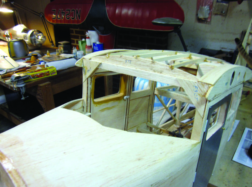
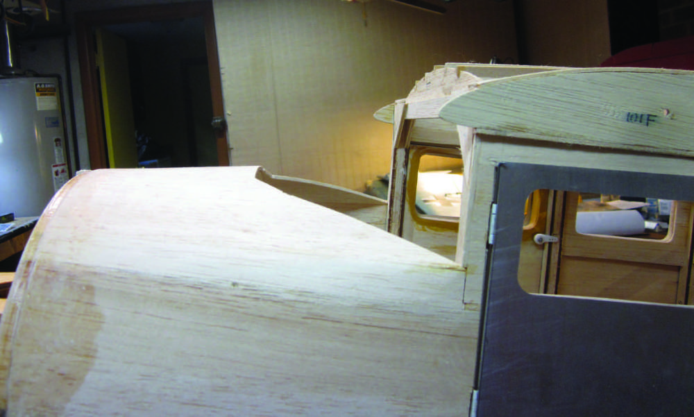
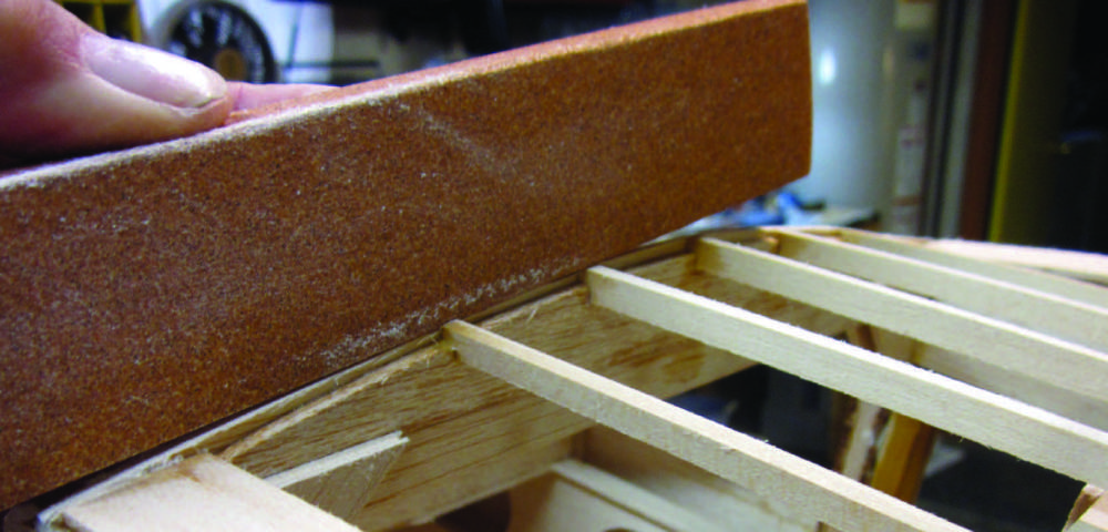
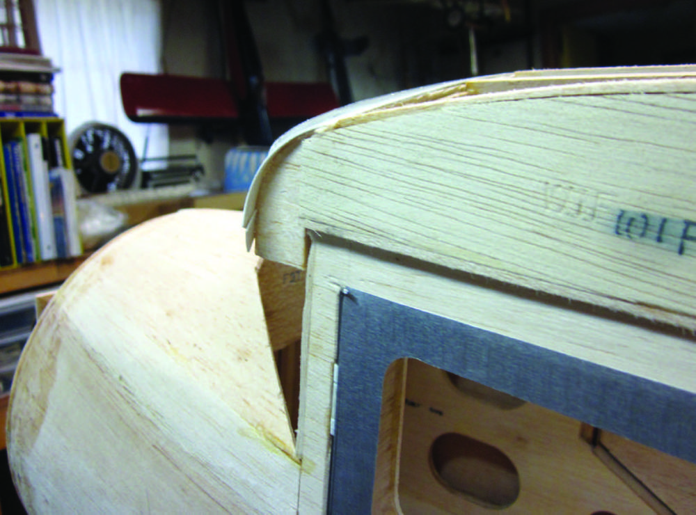
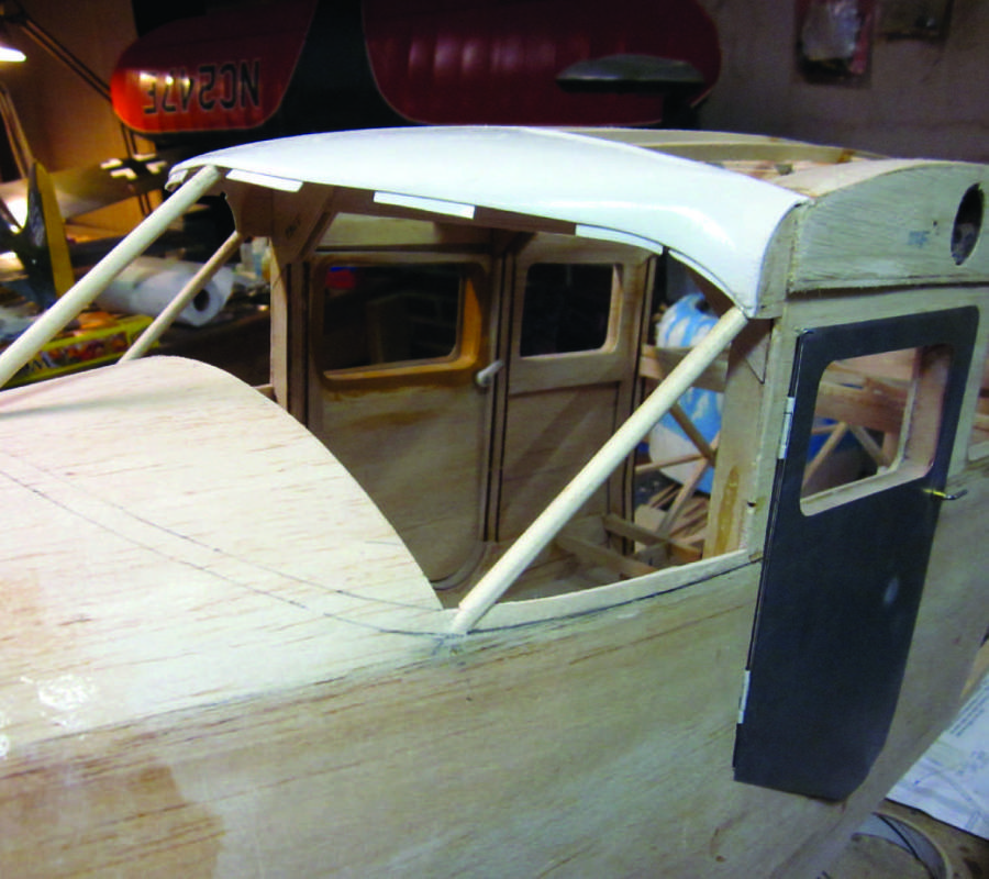
This is the cabin front/windshield area as we left it last time. There are short extensions of the plywood root ribs left to be cut off and the top cowl/deck must be trimmed to fit the correct scale outline. Right: From the side you can see the protrusions of the root ribs ahead of F-3. These get cut off flush.
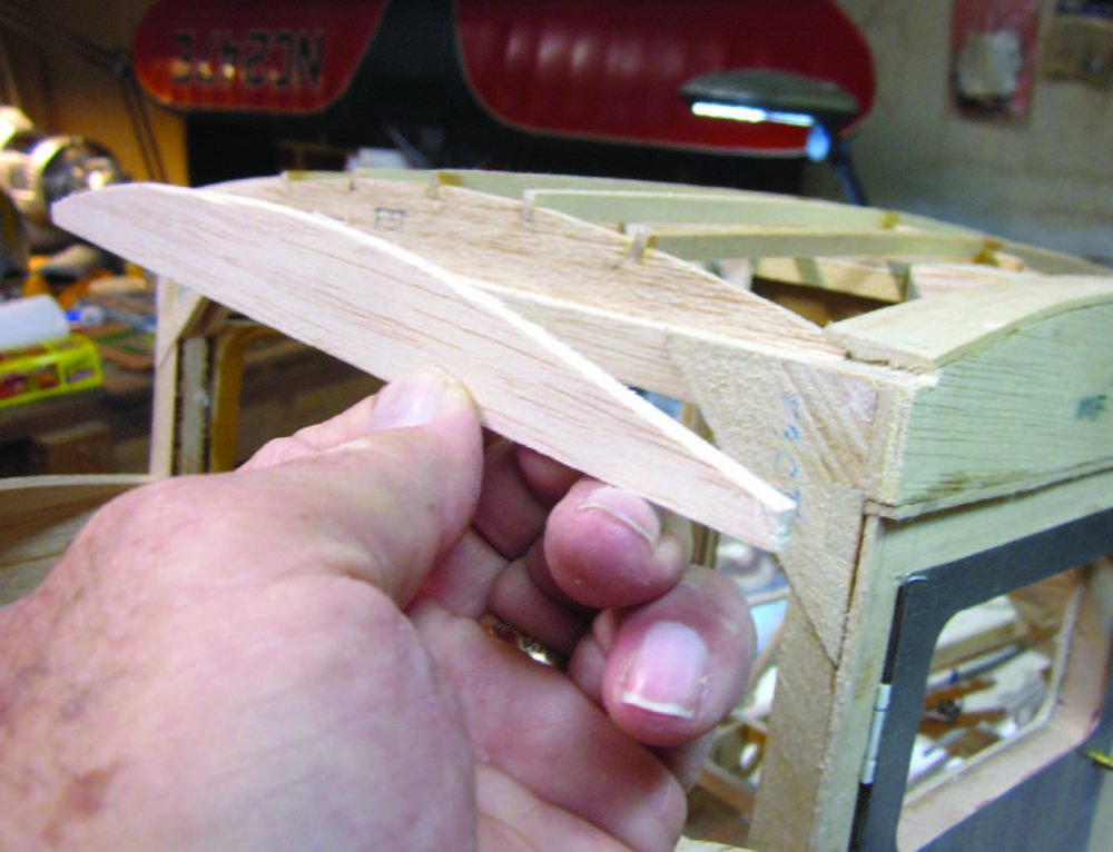
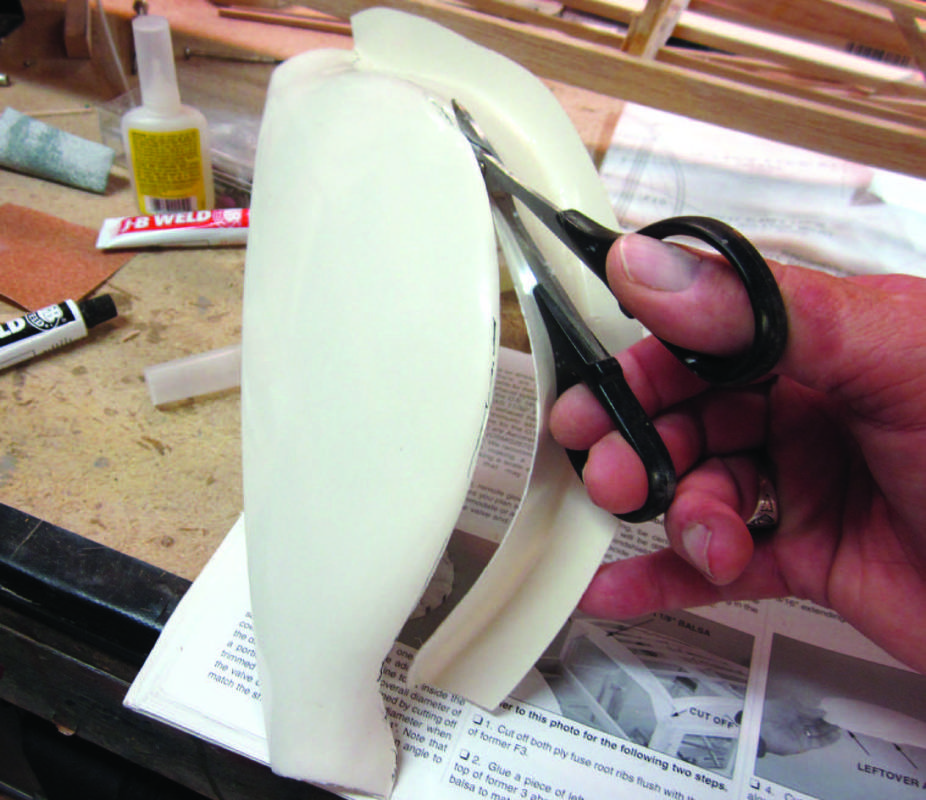
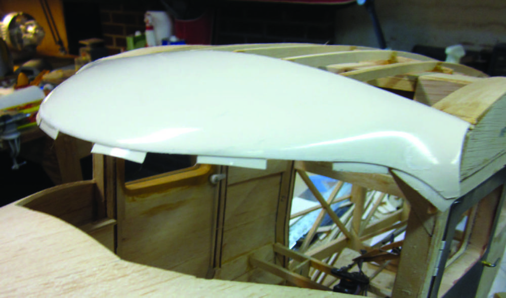
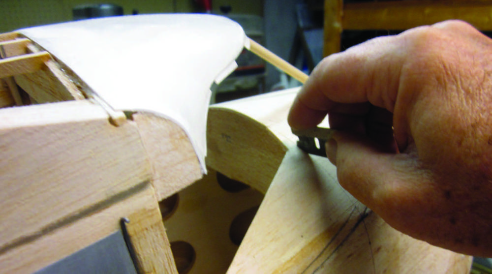
The next step is to make a “duplicate” former to match the top of F-3 from extra 1/8-inch sheet balsa and shape it to an exact fit with the top (outer) faces of the cabin top stringers. I’ll glue it later. With the wing panels temporarily in place per step three, I’ll then replace the little cut-off rib fronts in alignment with the wing root structure.The molded ABS cabin top has to be cut out of the plastic sheet matrix. I used short, curvedblade scissors, cut oversize and then sanded the part outline to an exact fit.
I’m using 100-grit production paper on a block to true-up the fronts of the cabin stringers and F-3 prior to gluing that duplicate former in place.
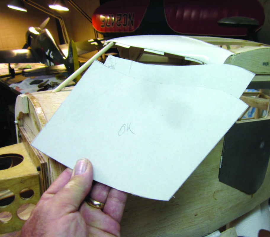
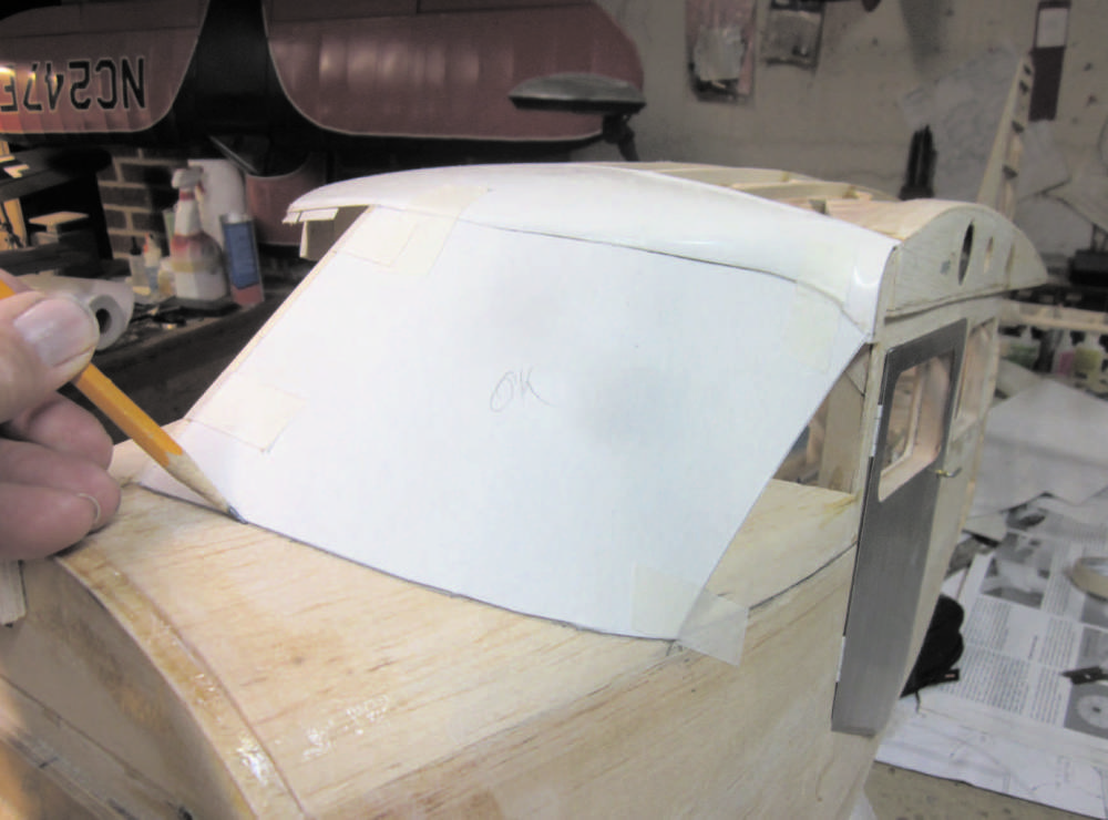
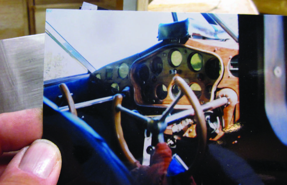
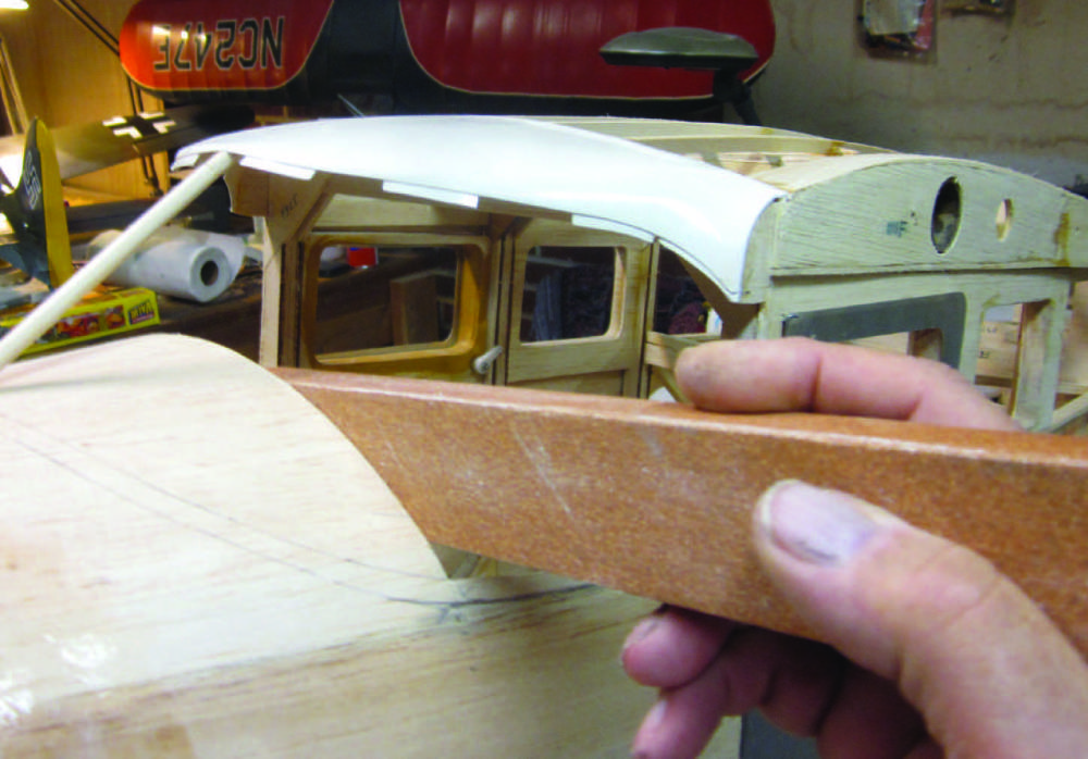
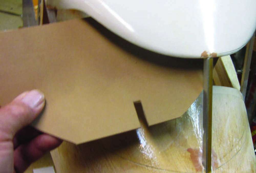
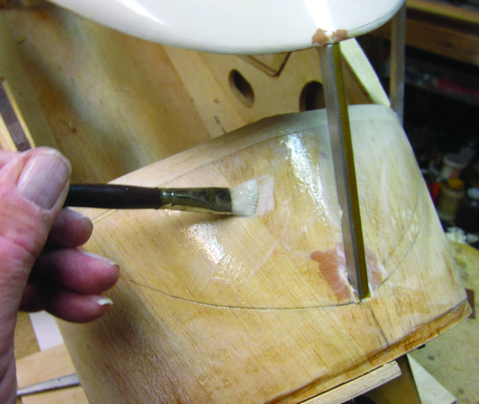
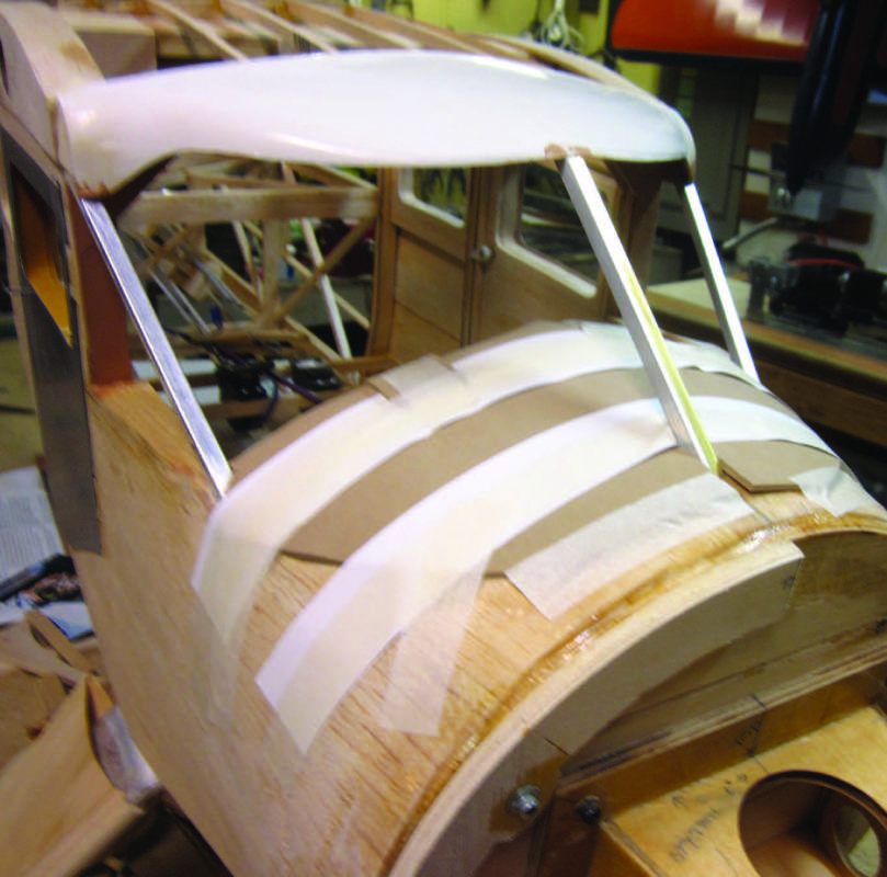
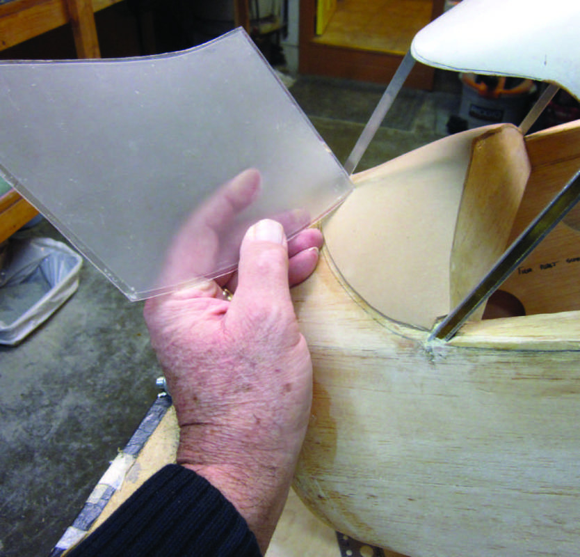
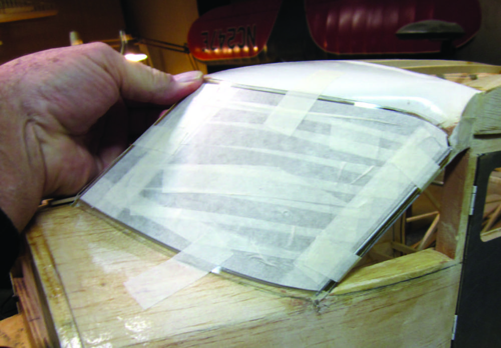
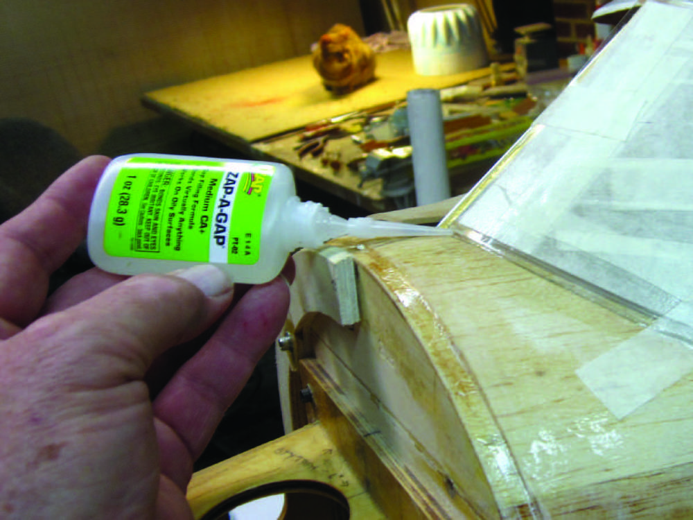
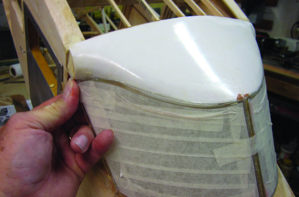
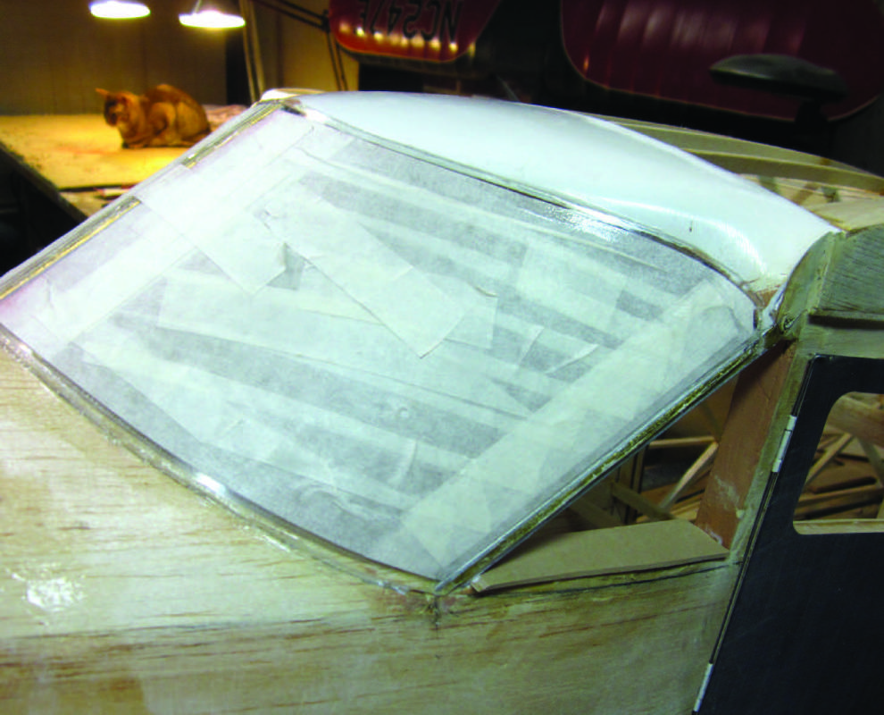
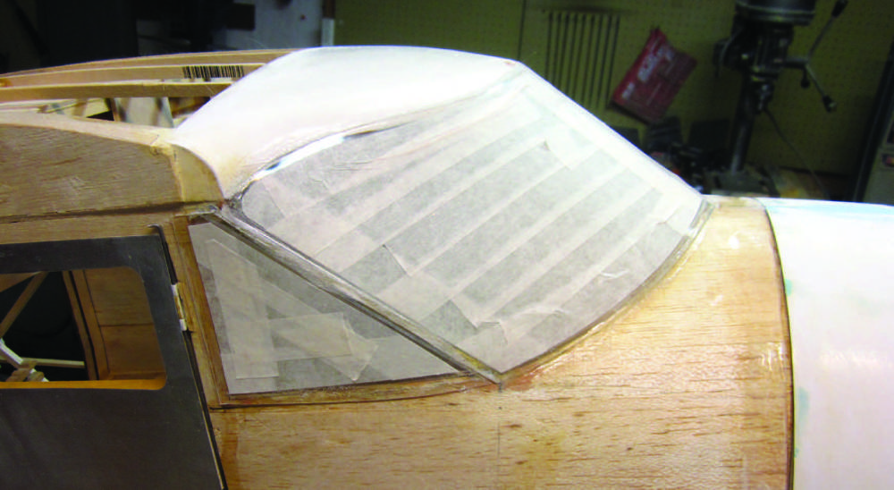
I have used ZAPAGAP to glue the cabin top in place. The most important thing here is to align the top rear edge precisely with the top/outer faces of the stringers. The overhang at the sides gets trimmed off later.The instructions suggest using several scraps of ABS sheet as windshield backing plates. I ZAP’d these to the inside front of the cabin top. I used a dowel front windshield brace cut per the plan to space the front corner of the cabin top up from the deck, but it’s out of the way in this shot.The instructions suggest that you use the windshield patterns cut from the plan to define the clear plastic panels. I found these patterns to be just a bit small, so I made new ones from card stock. This is when the essence of the “make it fit” part happens.With that pattern cut as accurately as I could get it, I taped it in place and marked a line along the lower edge to define where the windshield will meet the deck.This is a photo of the cabin interior of a full-scale Stinson SR-9 showing the actual layout of the instrument panel and top deck that I want to replicate.I “eyeballed” the contour of the inner edge of the inside top deck and cut away the excess balsa nose sheet to match the photo.The best way to get a square, accurate edge where the panel top will go is with that sanding block.These are the dowel windshield posts in place. After some thought I decided that they did not look right. The length used was right, but the shape was all wrong, so I cut them out and replaced them with 1/4-inch square brass tubing from the K&S rack at the local hobby shop. You’ll see those in the next shot.With the “real” braces in place, I cut a sheet of craft paper that matches the appearance of the upholstery on the top deck in my photo.I’m using a brush to spread paper laminating glue (from the craft store) over the top deck where the simulated upholstery will go.Lots of masking tape holds the paper in place while the glue dries. Be sure that the material you choose will not tear when you remove the tape or use strips of scrap paper between the upholstery fabric and the tape to protect it. Don’t try to use a ZAP product here…you need lots of time to position the material without having the adhesive grab too soon.Now the glue is dry and the tape has been pulled. Note that the opaque protective sheet is still attached to the clear plastic sheet as it comes out of the kit box. You can’t rely on that stuff to protect the plastic during real construction, so I removed it and used masking tape to define and protect the area of the windshield panel that is to remain clear. I left a margin of about 3/16-inch around the perimeter for attachment.Here’s what that looks like. The left front windshield panel is all taped, placed in position, and secured by additional temporary strips of tape.I worked my way around the windshield panel perimeter with ZAP-A-GAP and Zip Kicker, a few inches at a time, to permanently glue it in place. As a section is ready I pull the temporary tape holding it and add more ZAP.Here I have the left front section all glued in place and I’m fitting the right half…notice the masking tape still in place across the front post.Here’s the left front section all attached. I’ve left a margin all around the edges that corresponds to the scale width of the sheet metal cover strips on the full size airplane. Later I’ll add more layers of masking tape to these edges to define the thickness of a layer of Lite Fill epoxy that I’ll sand and finish to represent them.This is the other side with the rear/side windshield panel in place. I’ll continue with the scale detailing that I just mentioned after the covering and base finish are on the model.
That’s all we have room for here, but there’s more. Go to
http://www.rcmodel.com/2013/01/building-the-stinson-sr-9-17/ to see all the rest
of the details of Stinson blog No. 17.
 Fly RC Magazine WE LIVE RC