 Fly RC Magazine WE LIVE RC
Words and photos by Gary A. Ritchie
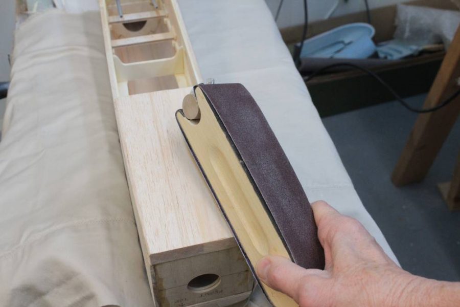
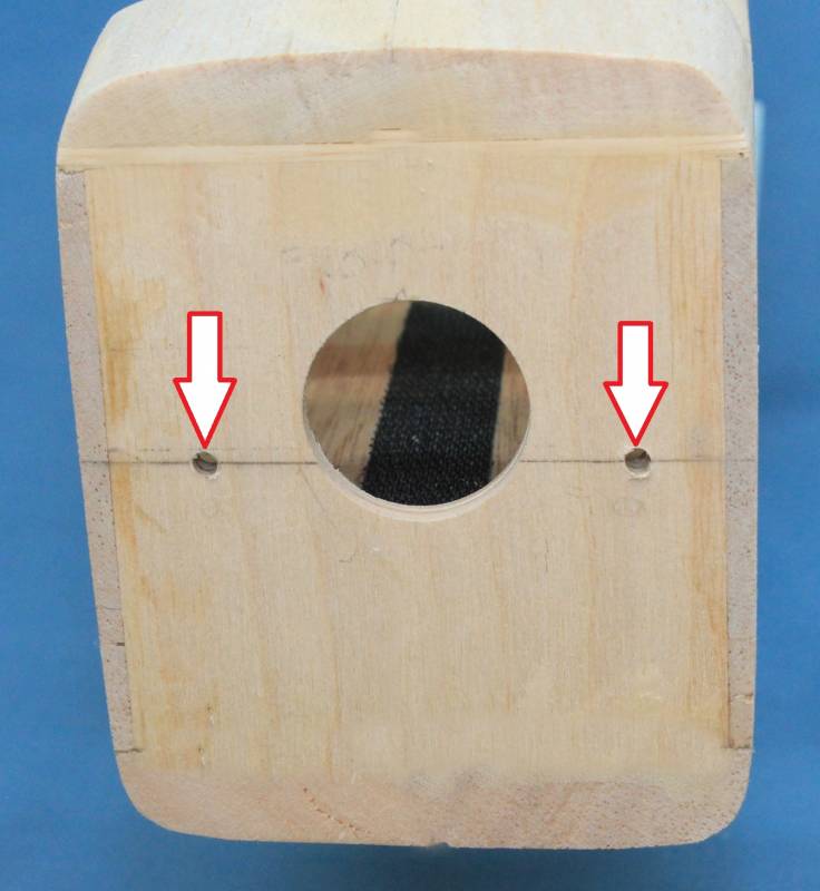
Now it’s time to build a fiberglass cowling that will fully enclose the electric motor in our Ultra Sport 60. Before we begin, sand the front of the fuselage into a smooth oval shape (Figure 1). Then draw a pencil line across the front center of the firewall and drill two 9/64” holes straight down through the firewall 5/8” in from the fuselage sides (Figure 2).
Building the cowling involves two steps: (1) making a mold from blue foam, and (2) building the cowling over the mold using strips of fiberglass cloth. When this is done, the foam mold is cut away leaving the fiberglass cowling. Let’s take them one step at a time.
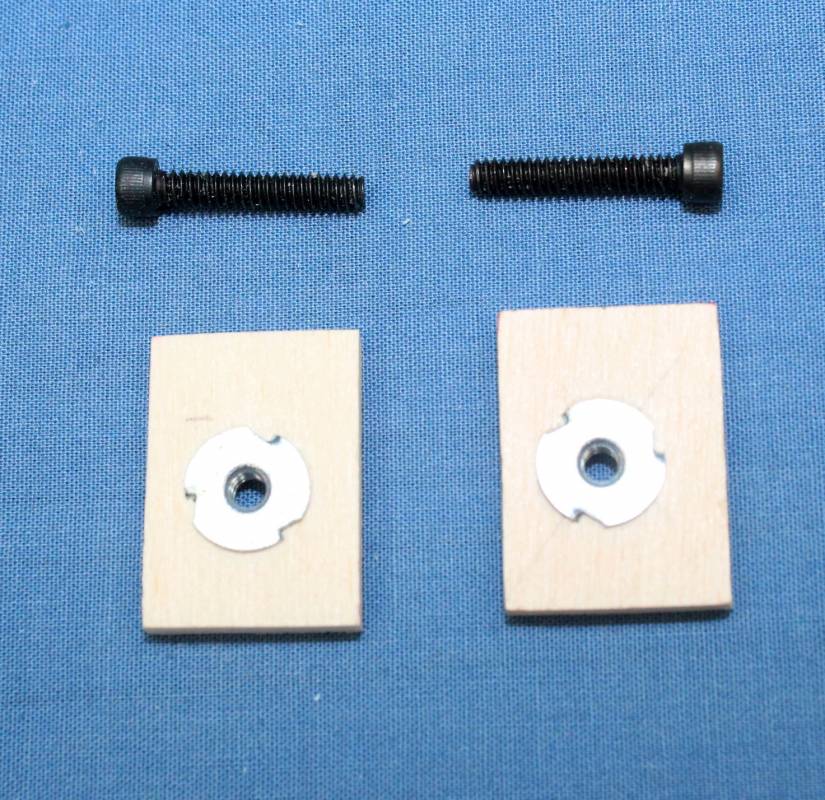
Making the mold. To make the mold you will need a 1-foot square sheet of 2” thick blue foam (you can buy this at a hardware store, but I was able to get some scrap foam from a fellow modeler), two 4-40 blind nuts, two 4-40 x 5/8” long socket head cap screws, two small pieces of scrap 1/8” plywood, and some 20 minute Epoxy.
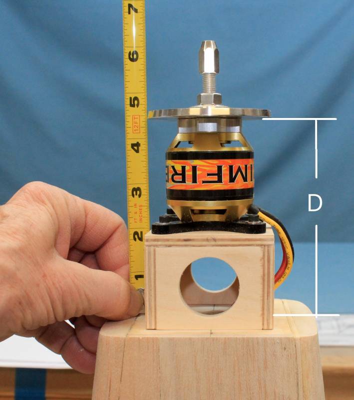
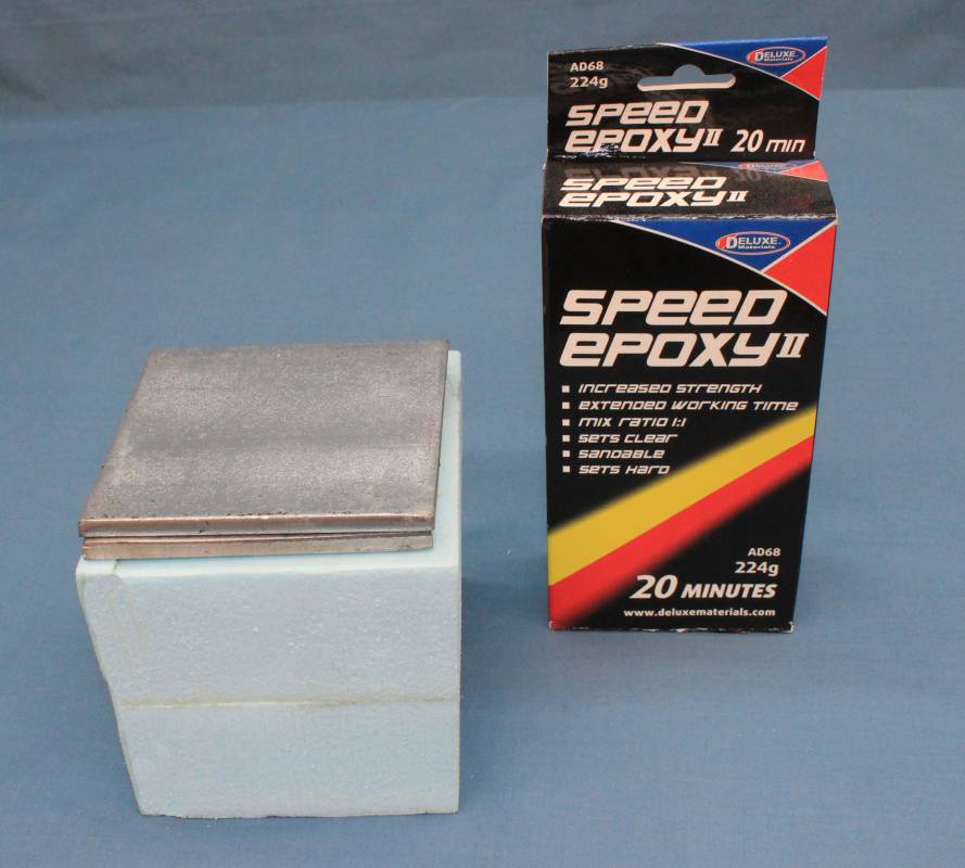
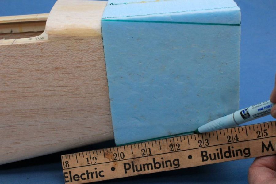
Bolt the motor to the motor mount and set the assembly on top of the firewall, center it up, and then measure the distance (D) from the front of the firewall to the back of the prop spinner plate (Figure 3). With my plane, D was 4 3/8”. Then cut two blocks of foam exactly 4¾” x 4 3/8” (modify this if D is not 4 3/8”). I used a band saw for this. If you don’t have a band saw you can use a table saw or even a hand saw with a miter block. The idea is to cut the pieces as square as possible. Then glue them together side to side and hold them firmly in place with a couple of metal weights while the glue dries. I used Deluxe 20-minute Speed Epoxy II for this step (Figure 4). This will give you a block of foam with the dimensions: 4 ¾” x 4 3/8” x 4”.
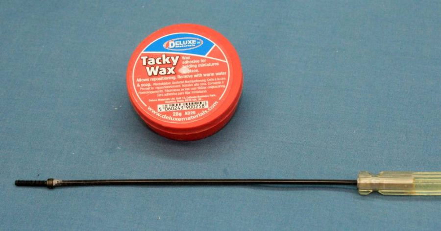
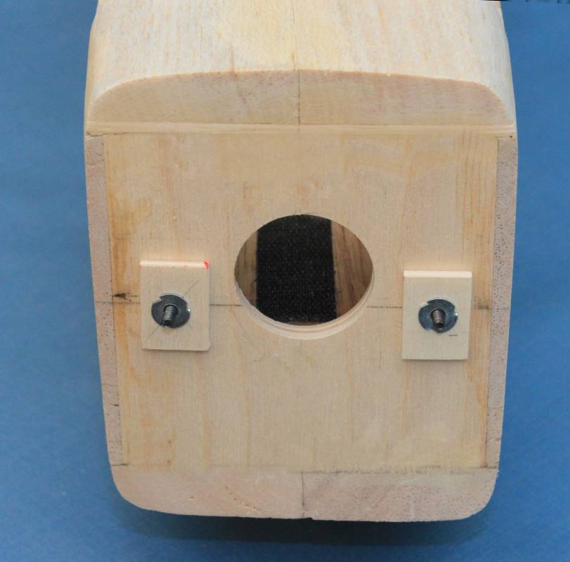
Now cut two pieces of 1/8” scrap plywood to about 1” x ½” and drill a 1/8” hole in the center of each. Mount one of the 4-40 blind nuts in each hole (Figure 5). Then feed the two 4-40 bolts through the holes you drilled in the firewall (Figure 2) from inside the fuselage so that the ends protrude through the nose. You can make this easier by putting a blob of Deluxe Tacky Wax on the tip of your ball driver to hold the screw as you insert it into the front of the fuselage (Figure 6). A Glue Stick will also work but not as well. Then bolt each plywood block firmly to the front of the firewall (Figure 7).
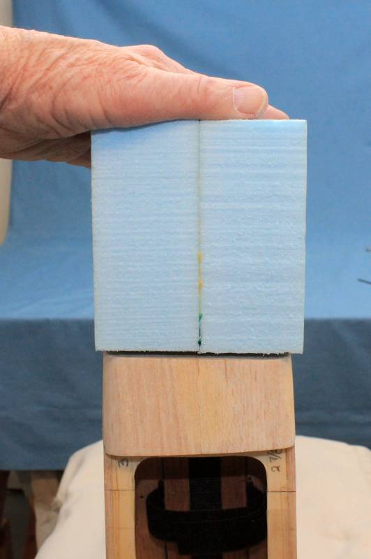
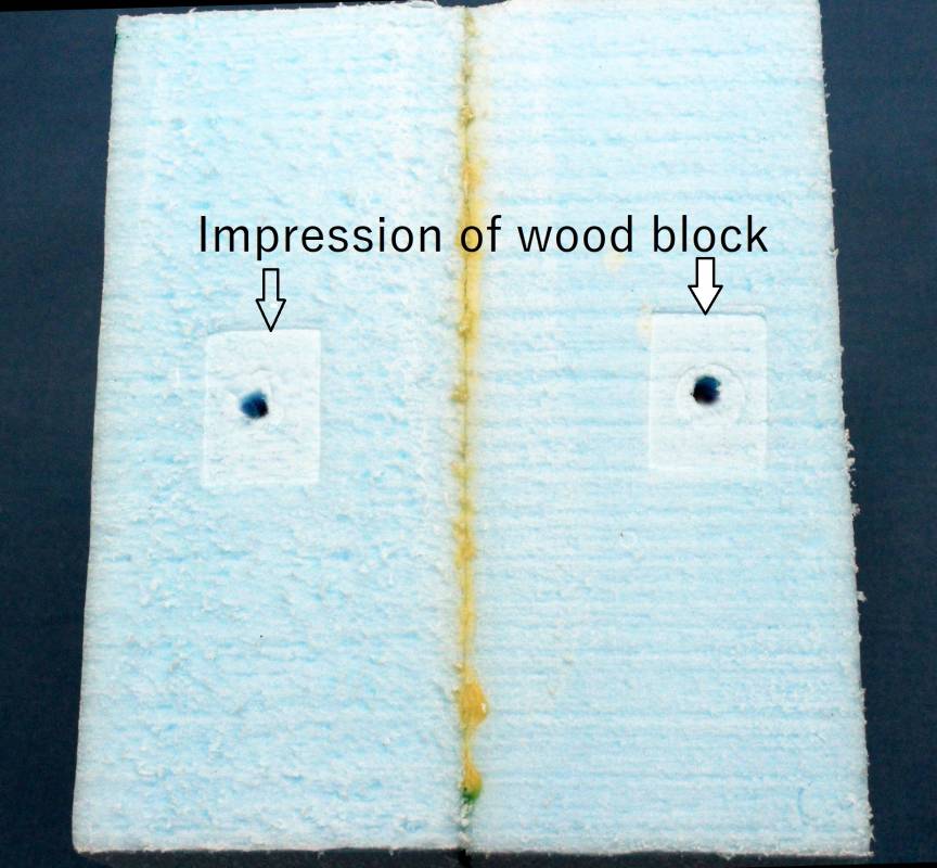
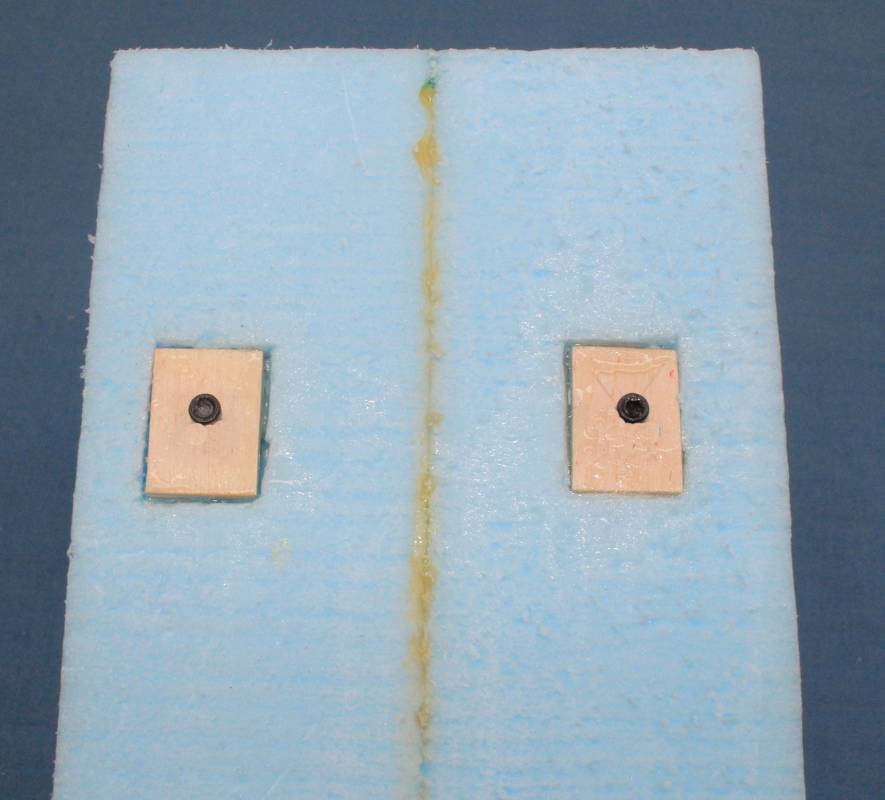
Now firmly fasten your fuselage into an upright position (I used my Shop Mate) and press the foam block straight down on the front of the firewall (Figure 8). This will mark the locations of the ply blocks on the bottom of the foam block (Figure 9). Remove the plywood blocks from the firewall, cut out the impressions in the foam down to about 1/8” with your hobby knife and Epoxy the plywood blocks into these cutouts (Figure 10). These will be the mounting points for the foam block as we fasten it into place on the fuselage and begin shaping it. Then screw the foam block firmly to the front of the fuselage, again running the bolts in from behind the firewall as you did earlier. Then draw lines on the block to extend the outlines of the upper and lower fuselage (Figure 11).
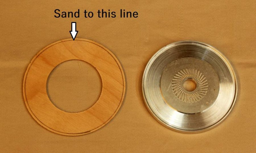
Find the round 1/8” plywood spinner ring provided in the kit. Set the spinner backplate from the spinner you plan to use on the ring and use it as a template to draw a circle around the spinner ring. Then sand the ring to match the diameter of the spinner backplate (Figure 12).
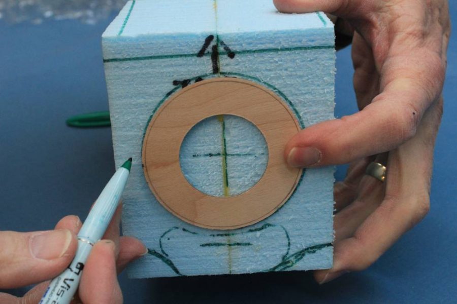
Mark the center of the front of the foam block. Use the plan drawings to determine exactly where the center will be. Then place the spinner ring on the center of the foam block and draw a circle around it (Figure 13). Note that I am planning to add an air scoop beneath the spinner, so you need to draw that in as well.
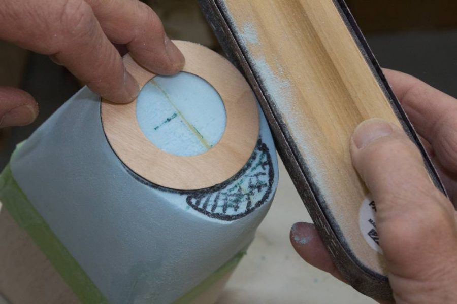
We are now ready to begin shaping the mold. Using the front edge of the fuselage and the round forward edge of the block as guides, send the block so that it gradually contours from the fuselage down to the shape of the spinner ring – leaving a place for the air scoop beneath it. Finally place the spinner ring at the front of the block and make sure the foam exactly matches it. If not, do some final sanding to make it perfect (Figure 14). Note in Figure 14 the area that I left for the air scoop. To do the sanding I initially used #80 grit sandpaper. Be careful with this because it can tear large chunks out of the foam. To finish I switched to #120 grit to smooth out the mold. Keep working on it until you get it as smooth and uniform as you can.
This completes construction of our mold. Next time we will use it to fabricate the fiberglass cowling. Until then remember to take your time and enjoy doing a good job.
LINKS
