 Fly RC Magazine WE LIVE RC
Nitro Planes Flying Cat 90 R/C Pusher Jet
Made for the adrenaline junkie!
Author: Craig Trachten
Photographer: Walter Sidas
BASICS
MANUFACTURER: Nitro Planes
DISTRIBUTOR: Nitro Planes
TYPE: Jet-style pusher prop ARF
FOR: Advanced pilots
PRICE: $119.95
SHORT DESCRIPTION:
Nitro Planes Fly Cat 90 is for those like me that want the Jet feel of flying without having to mortgage your lungs to fly turbines. Flying off a grass field posed some problems but the effort to overcome them is well worth. For me, this is not an every day flyer but she’ll come out of the hangar whenever I feel the need for an adrenaline rush. Have fun, fly safe.
ASSEMBLY
Surprise, surprise… construction starts with CAing the ailerons to the wings. Would be nice if someone would step out of the box and start with something other than the ailerons but it is what it is. Open the covering for the servos. I go in on a 45 degree angle inward which gives me a clean opening. The aileron pushrods are typical clevis/fastlink design. The rudder and elevator are attached just like the ailerons. The cutouts for the rudder/aileron servos are factory cut in the fiberglass fuse and pushrod construction mimics the aileron rods. Attaching the horizontal stabilizer to the fuse requires some drilling. Drill two holes, factory marked, and insert blind nuts. The stab is secured with 2 bolts. Quick, easy, no epoxy ooze to clean up. The next construction phase is installing the landing gear, nose and mains. Experience suggested that I should have taken care of something pre-first flight but I didn’t. I should have done some pre-emptive epoxying. On my first attempt to take off, I hit the proverbial bump in the road and ripped out the bulkhead that the nose gear is attached to. Fortunately, it came out clean, so repair was quick and easy. After epoxying the bulkhead back in place, I mixed up another batch with micro-balloons. A nice fillet around the bulkhead is insurance that this won’t happen again. As long as I reinforced the nose, why not the mains so they too, got a healthy dose of epoxy.
I’m sure everyone has their favorite way to mark/mount their engines when dealing with individual rails. This is the way I found easiest. I first mount the rails to the engine. Each rail is clamped to the engine making sure I have the proper distance from firewall to thrust washer, mark, drill, and secure. Once both rails are mounted, I place the engine on the firewall, shift into position, and mark the mounting holes. Nitro Planes made this a bit easier by having the centerlines marked on the firewall. Drill and install the blind nuts. Remove the rails from the engine, secure them to the firewall, then reattach the engine.
Getting near the end of the printed documentation, I just scanned ahead to check out what was left to do. To my surprise, there was no mention about installing the fuel tank. Really no big deal as I’m sure you don’t need to be shown how to build a tank. Since there is enough room in the fuse to get half your arm in, installing the tank even with the engine attached, is not a problem. My normal tank install routine would have eliminated any issues anyway. When I install a tank, I do not guess how long to make the lines. I feed the end of the full length line, be it off a roll or from a pre-packed 2 foot length, through the opening in the firewall. I then attach the lines to the tank, and then pull the lines back as I move the tank in place. For the record, I always build my tanks with 3 lines; 1 to the carb, 1 to the muffler for pressure and the 3rd. line is for fill and defueling (that line is clunked too). The other thing I always do is use different colors for each line. It only took me one time to mix up the lines to move to multicolor.
Coming down to the home stretch with the assembly, it’s time to bolt the wings to the fuse and attach the wing tips. It is easier to make sure the wing tips are at the same angle with the wings on the fuse. The final assembly instruction before securing the canopy and belly hatch is to install the battery and receiver. I ended up having to put the receiver battery on an extension and stuffing it in the tail to achieve the proper CG. Screw down the belly hatch and canopy and it’s time to go flying!
 |
 |
 |
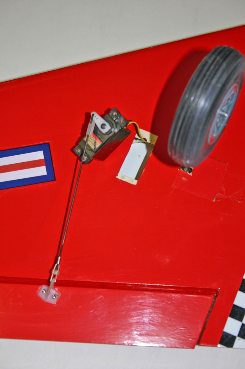
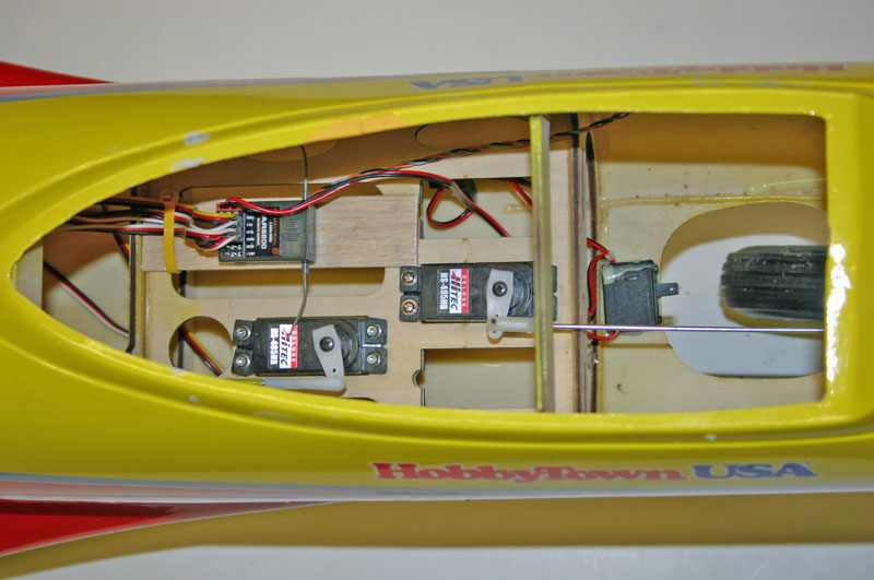
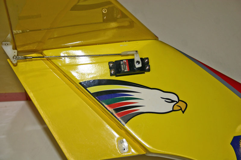
| The Hitec HS-485HB aileron servo is removed from the servo pocket. Notice the DUBRO wheels I installed. | The Hitec HS-485HB throttle and nose wheel steering servos are installed under the canopy as well as the receiver and radio switch. | |
 |
 |
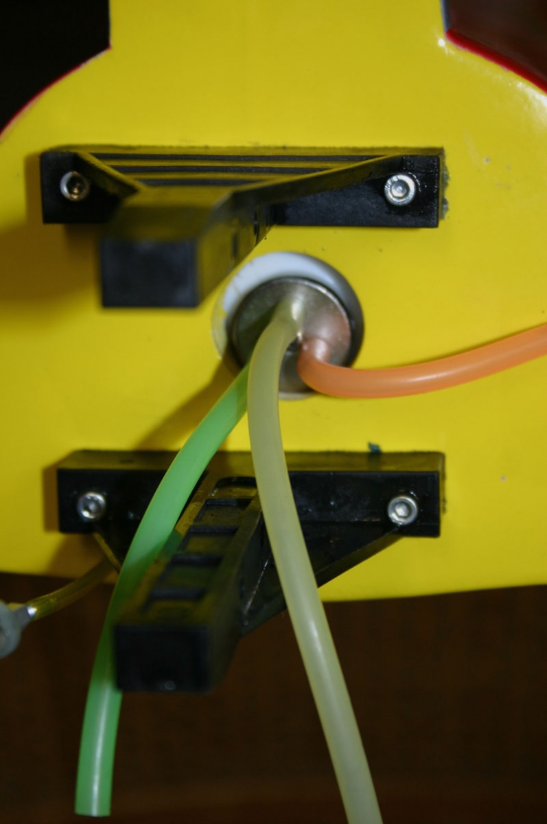 |
| The Hitec HS-485HB elevator servo is installed in the vertical fin. | The fuel tank lines come through the firewall. I am using three lines, for vent, supply and fill. | |
 |
 |
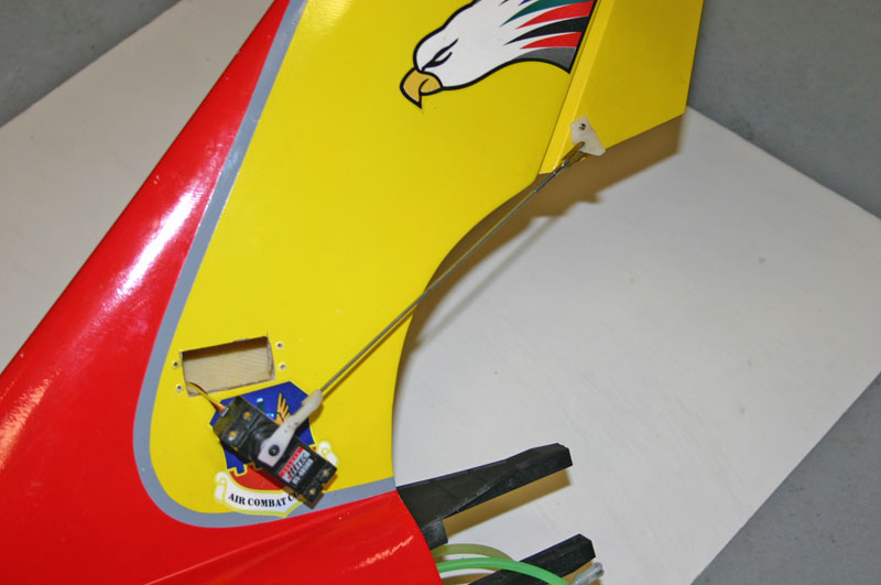 |
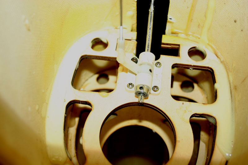
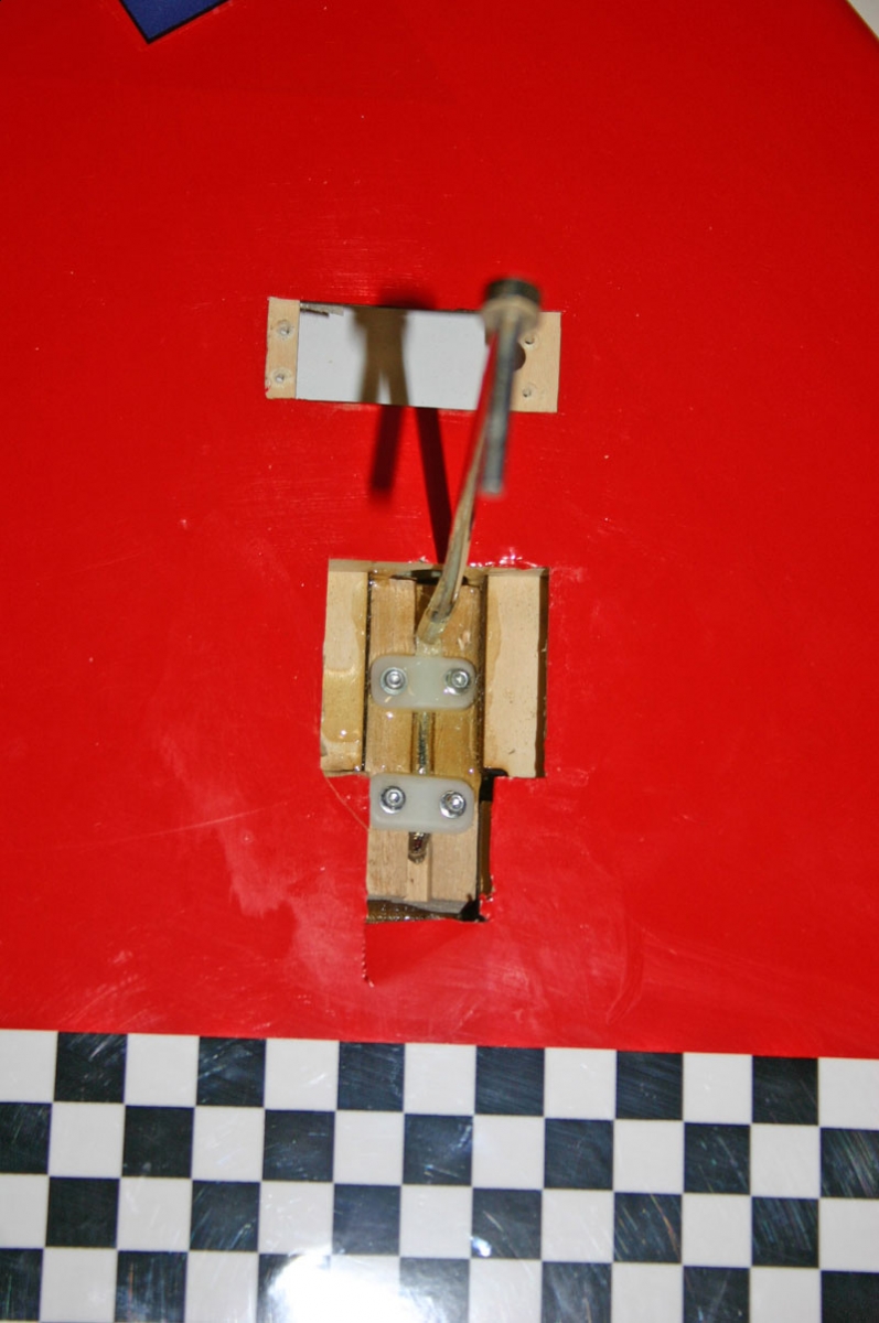
| One rough landing caused me to have to reinforce the bulkhead. | I also reinforced the landing gear block to strengthen the gear because of my rough field. | The rudder servo is mounted in the opposite side of the vertical fin as the elevator servo. |
 |
||
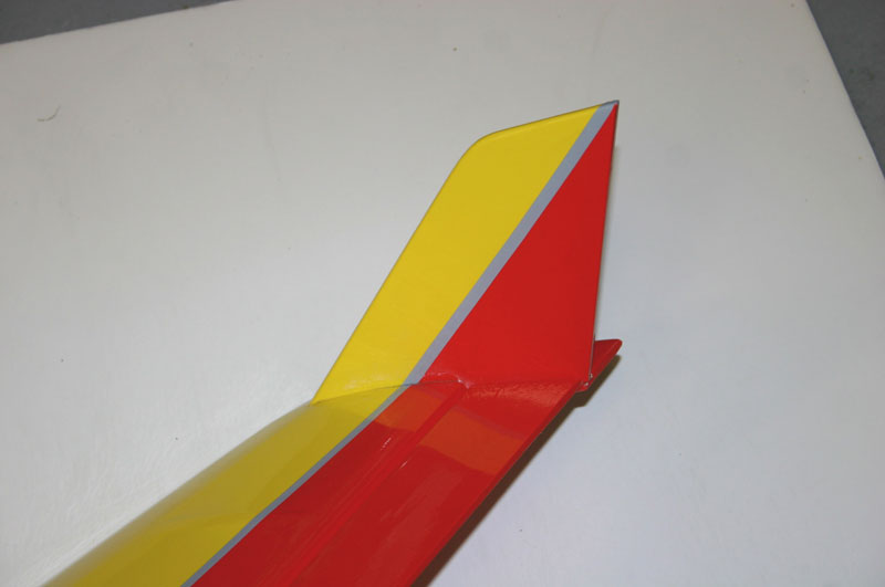
| The wing tips are epoxied in place. |
Links:
HITEC
HOBBICO
JR
MASTER AIRSCREW
NITRO PLANES
SPEKTRUM
