Fly RC Magazine WE LIVE RC
|
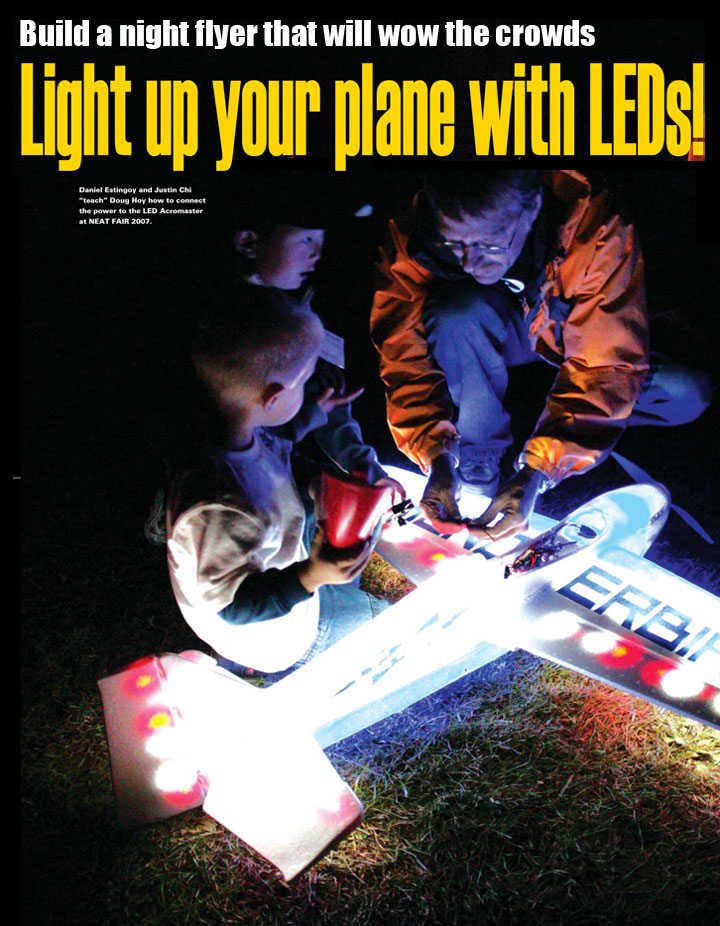
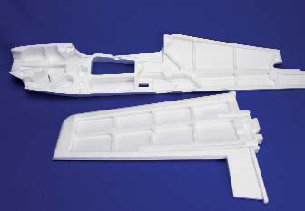
Every now and then, I hear a little voice that commands me to do things. My little voice came up with a winner recently. I had a Multiplex Acromaster kit waiting to be assembled. I noted that the fuselage and wings are actually made in a clamshell fashion with hollows inside to save weight. Furthermore, the Elapor foam glows very nicely when illuminated from within. These hollows offered very neat and tidy little cells that my voice thought would work well to contain light-emitting diodes (LEDs) to make a great night flyer. My voice and I set out to make that happen. Here are the results and a quick how-to.
LET THERE BE LIGHT!
LEDs are amazing little electronic devices that produce light from an electric current that is nothing less than astounding. They require a very precise current, and you cant let them have too much current or they will go the way of the overfed goldfish in a s e c o n d – g r a d e classroom. In short, you need to control the voltage and current that they receive in order to make them work and last. LEDs can be difficult to use in RC airplanes because they require a stable voltage supply; this is often hard to achieve, as the motor is doing its best to lower the batteries voltages during the entire flight. An ideal way to control the voltage is to use a battery eliminator circuit (BEC) to drop the voltage from a higher-voltage motor pack to a stable level that meets the LEDs needs. There are a number of regulators on the market, but one offers a unique advantage: the ability to set the output voltage to voltages above the usual 4.8- to 6V range. Castles CCBEC lets you select the voltage in 1/10-volt increments up to 9 volts. This is useful in an LED application because it allows you to use more than one LED in series. Unfortunately, an LEDs current must still be controlled by placing a resistor of a precise value in the circuit, or it will simply draw as much current as it can until it burns up.
LED MATH Degrees in philosophy and law werent much use to me (once again), so I bribed some of my coworkers who are electrical engineers with lunch (BBQ) to get them to teach me the way of the LED and to reveal a good source of LEDs for this project. We figured it would take a bunch, and they have had good results from some eBay vendors. I was truly amazed at the variety of colors available. LEDs come in standard red, green and amber hues, but they are also available in brilliant white, purple, orange, blue and UV, among other colors. A second lunch (Mexican) got me the required information on how to determine the required resistances of the particular LEDs. LEDs are not all the same; they require slightly different voltages to operate. This voltage is normally given in the specifications as theforward voltage. The trick is to provide that forward voltage as conveniently as possible. There is some math required here, but never fear: there are LED calculators on the Web that will do the calculations for you. My coworkers shared Ohms law with me: V = IR. (The lawyer in me cringed slightly at the name.) This means that the voltage is equal to the current multiplied by the resistance. You will need to get the specific forward voltage and max forward current of the LEDs that you plan to use. This information is all available on the eBay page where you buy the particular LEDs. It will vary with individual type and color, so be sure to verify that you are using the proper values. Do not assume that the values for the LEDs that I suggest below will be the same as yours. The white LEDs that I used were 3.4 forward volts and 30mA peak forward current. I figured that Id like to run at least two LEDs in series to cut down on the number of resistors Id need. I can do that because the resulting voltage of two 3.4V LEDs in series is 2×3.4 = 6.8, which is less than the 8V input that I had selected for the CCBEC. (I cant run three because 3×3.4 = 10.2, which exceeds my input voltage.)
|
|
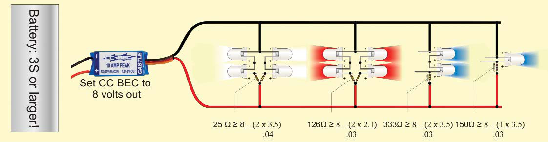 Parallel circuit with multiple LED series and single sets. Mix and match number of LEDs and colors as desired. Each color and series combination may require a different resistor value. Set the CCBEC to an 8-volt output, and use resistors as described in the article to reduce current to suit the characteristics of your particular LEDs. Increasing the number of LED sets along the parallel lines will draw more current (amps) but the voltage will be relatively stable. Parallel circuit with multiple LED series and single sets. Mix and match number of LEDs and colors as desired. Each color and series combination may require a different resistor value. Set the CCBEC to an 8-volt output, and use resistors as described in the article to reduce current to suit the characteristics of your particular LEDs. Increasing the number of LED sets along the parallel lines will draw more current (amps) but the voltage will be relatively stable. |
|
|
Use the following formula: RED WHITE BLUE Typical values from LED vendor site. *Use caution with units. The LED vendors website may list If in mA (milliamps). The If term in the equation requires the figure be in amps. Divide the mA by 1000 to get the proper value. The math for my particular LEDs works out as follows: Resistance needed = [8 – (2×3.4)] ÷ 0.03 = 53 ohms
This means that you will need a resistor with approximately 53 ohms of resistance to use two of these LEDs in series with an 8V input. Use a resistor in the range of 53 ohms, ± a few ohms: say 50 to 60 ohms. Simply order the required resistors from a source such as Digikey. See www.castlecreations.com for more detail on ordering LEDs and resistors.
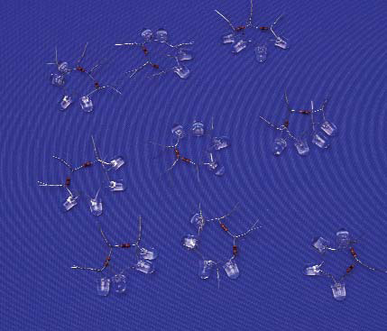
Make a bunch ofsnowflakes. They are easy to make, and you can bend
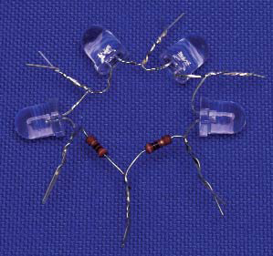
A finishedsnowflake made up of two series LED pairs joined in parallel.
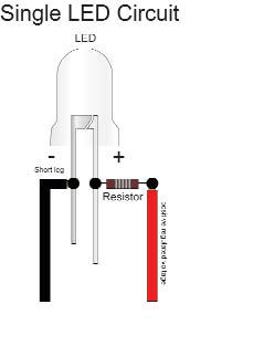
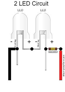
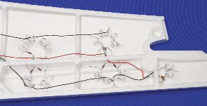
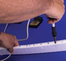
TWIST AND SHOUT Its time to start wiring. Turn up the music, grab a beverage, pull up a chair and start twisting pairs. I twisted the legs of the LEDs and resistors together like so many twist-ties. My 3-year-old son found the process fascinating. You will need to pay careful attention to the polarity of the LEDs and to the values of the resistors. Three-year-old assistants generally are not paying attention to these matters and rather enjoy dumping the bags of components into a big pile. Dont do this. For a series of two LEDs, connect the negative (short) leg of the first LED to the positive leg of the second (the positive leg is the longer of the two). Twist the resistor to the free positive leg. If you wish, you can join two of these series units by connecting them in parallel; the resistors go together and the negatives go together. The finished circuits look like snowflakes. The leads end up sticking out a bit. Dont worry about this, as they make a great means of securing the snowflakes in the wing foam: just press them into place, and they generally stay put. I found it wise to test the snowflakes before I soldered the parts together. It is very easy to correctwrongs before they are permanently joined with solder. Just apply the leads from the powered CCBEC, and see whether they work. Once you are satisfied that the pairs are arranged properly, solder the joints together. This is merely a matter of touching the iron and the solder to the various twisted leads. This all goes very quickly. The next step is to wire the snowflakes together in parallel. I used the lightest wire that I could find in my shop; its a flexible 24-gauge with very soft insulation. I started with black and red to keep things orderly. The positive side of the snowflakes—the one with the resistor—always goes to the positive wire and the negativeleg of the snowflake to the negative wire. I found it really simple to use my fingernails to pull the insulation on the wires back and then wrap the exposed portion around the stiff resistor or LED legs. A quick touch with the soldering iron and a bit of solder, and that snowflake is good to go. The final piece of the puzzle was figuring out how to illuminate the large control surfaces. I found that I could make nice tunnels for the LEDs in the control surfaces and othersolid portions of foam by turning the heat on my soldering iron down to the coolest setting and then pushing the hot iron into the leading edge of the control surface as far as I dared. This leaves a nice conical hole in the foam that is a perfect place for an LED or two. Take care to measure and plan these holes; they can really ruin the project if done too casually. Note that the LEDs used in the control surfaces must be wired individually; trying to rig multiple LEDs on the circuits with the resistors is far more difficult than simply adding a resistor to each LED. You can use the formula described above to figure the resistor value that is needed. Be sure to use a very flexible wire to connect the control surface to the stationary fuselage; I ran mine along the length of the control surface to spread the wire flex across as much length as possible
|
|
 The ARF includes a functional scale tailwheel. The ARF includes a functional scale tailwheel. |
 The ARF includes a functional scale tailwheel. The ARF includes a functional scale tailwheel. |
|
EXPRESS YOURSELF
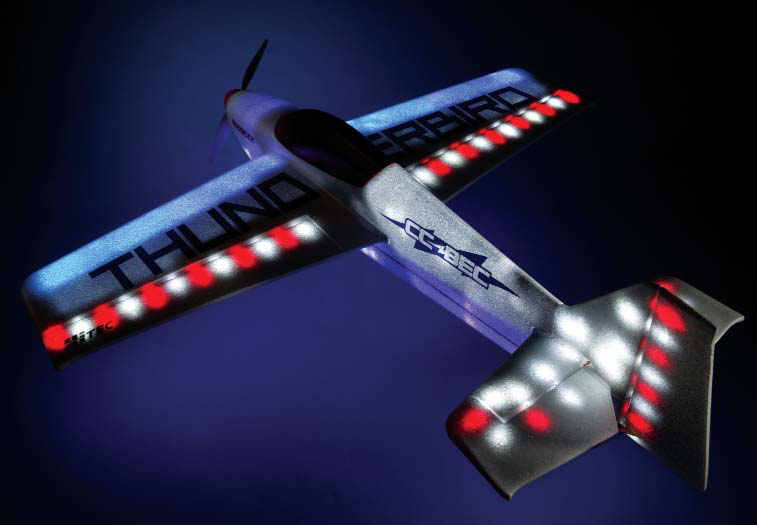
The internal cell structure of the Multiplex Acromaster lends itself well to color schemes. Use LEDs of several colors in the different cells for very nice color contrasts. Each cellcontains its color well, and the orderly geometry of the airframe allows many creative light patterns. Its incredibly easy to create wingtips of different colors or a two-color fuselage, both of which are important to maintain orientation in flight. Here are some considerations for choosing your color scheme. Bright white LEDs yield a brilliant white model that is very easy to see in the dark. Perhaps too easy. The bright white will affect your night vision. I found I owned the night sky at NEAT 07, as my plane was simply too bright; the other fliers couldnt see theirs! — Blue looks really cool on the ground, but it is not as easy to see at a distance. — Red works well. It is highly visible at a distance, and it doesnt harm your night vision. — Martian Green or bright orange would be a blast. Both offer a nice compromise between incredible brightness (white) and maintaining your night vision. UV light, or black light, LEDs are available, too. Sadly, the Acromasters foam doesnt fluoresce on its own. You could, however, use fluorescent paint and simply shine a few of these onto the surfaces for a cool effect with a minimum requirement of LEDs and added weight! The UV LED isnt very bright when viewed directly, so it wont blind you as the others do.
|
|
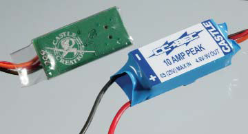 CCBEC and Castle Link USB Adapter. CCBEC and Castle Link USB Adapter. |
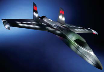 Funjets make great night flyers too! Funjets make great night flyers too! |
|
GO FLY! Once I had installed the LEDs, the plane had gained nearly 1 pound, much of it in the tail! I found that a larger battery pack shoved all the way into the cooling tunnel/battery compartment worked well and gave the desired CG. I feel certain that I could have made a very effective night flyer using half as many LEDs, and I could also have used a lighter wire than I used in the Acromaster; this is not critical, but lighter is almost always better. Even with the extra weight, the Acromaster flies very well. I am very pleased to report that it is quite a docile plane, even when it is carrying enough lights to make the Bee Gees proud. What sealed it for me was having the chance to let scale guru Terry Nitsch take the sticks of both the Acromaster and the Funjet at the 2007 JR Indoor Meet in Columbus. He couldnt get over how well these planes flew and how easy they were to see at night.
HAVE ACROMASTER, MUST TRAVEL Another great feature of the Acromaster kit is that the wings are removable. The instructions expect you to secure the horizontal and vertical tail surfaces permanently, but I found that they can be held in place with tape. The entire plane easily fits back into its great shipping box for travel and storage. Remember to use connectors on the wires between the removable parts and the fuselage. I also put Sullivan detachable ball links on the elevator and rudder pushrods so that I can simply snap everything into place when I get to my destination.
CONSTRUCTION TIPS It is tempting to use red and black wire to keep your polarity straight. Note that the red and black wire will be highly obvious wherever it isnt enclosed in the plane. It may also show through the foam itself. Consider using white wire throughout. I used a permanent marker to draw a black stripe on the negative wire. Some surfaces are too thin to bore out a holding cavity with a soldering iron. Cut a channel in the foam with an X-Acto knife, and then place the LEDs and the white wires in the channel; cover them with sign vinyl or colored tape. Some channels will simply not be deep enough for the larger LEDs. I found that I could grind the LEDs down on my belt sander to create a more square form factor that would fit the opening more conveniently. This also turns the LED into a more omnidirectional light source. The fuselage and wing panels are brighter when both halves are in place; the light is reflected in the cell and that area glows much more brightly when the halves are in place. Order the 200 pack for your main color. The trim colors can be achieved with smaller quantities.
CONCLUSION The future is ridiculously bright for this type of night flyer. I have already extended these techniques to the Multiplex Funjet with great results, and Im eyeing their fabulous Cularis for this treatment as well. Other foamies such as the ParkZone T-28 sold by Horizon Hobby would probably be a big hit, too.
Links Castle Creations, www.castlecreations.com, (913) 390-6939 Digikey (resistor source), www.digikey.com eBay (LED source), www.eBay.com LED Resistor Calculator, www.hebeiltd.com.cn/?p=zz.led.resistor.calculator LED Basic Calculator, http://led.linear1.org/1led.wiz LED Parallel Array Wizard, http://led.linear1.org/led.wiz Maxx Products International, Inc. (HiMax motor), www.maxxprod.com, (847) 438-2233 Multiplex, www.multiplexusa.com, (858) 748-6948 ParkZone (T-28), distributed by Horizon Hobby Distributors, www.parkzone.com, www.horizonhobby.com, (877) 504-0233
|
|