 Fly RC Magazine WE LIVE RC
Vintage Free Flight design converted to half size for Micro RC Born 1942, Reborn 2007
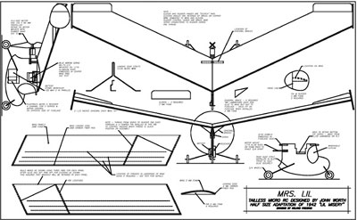
Way back 66 years ago I designed an original free flight tailless model I called the Lil Misery. Why that name? I cant remember! The plans and a construction article for it were published in the July 1942 issue of Air Trails magazine. Lil Misery spanned 50 inches and flew great. It was powered with a spark ignition Atom engine and was very stable.
I still have the original fuselage pod with the engine in good condition but the now uncovered wing framework is very fragile due to age. I also have another one of these models which was built for me, as a gift from Joe Beshar, when I retired from the Academy of Model Aeronautics many years ago. Both these models are great to look at and now that I am 84, serve as pleasant reminders of a neat WWII-era project that turned out well when I was only 18.
Until recently I was satisfied to only look at these old models and reminisce about what used to be. Now, however, Im deeply involved with micro flightthe smallest and lightest electric motor powered RC modelsand I got interested in building a much simpler half-size RC version of my 1942 model. I made this new one with a single surface foam sheet wing with a profile fuselage pod. Rudder control for turns and motor speed for climb and descent is provided via a lightweight RC system. The original 1942 model weighed 16.6 ounces; the new one is 1.4 ounces!
Balancing
The keys to successful flying wing model stability are Center of Gravity (CG) location and the amount of up elevator provided by the control surfaces on the wing tips. Theup elevator out on the tips provides the angular difference between the wing airfoil ahead of the CG and the part of the wing behind the CG that acts as a tail surfacethe angular difference provides the pitch stability needed for stable flight.
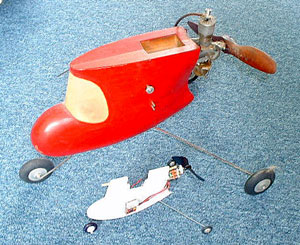
Original 1942 Lil Misery balsa fuselage pod with Atom glow engine alongside foam Mrs Lil fuselage pod
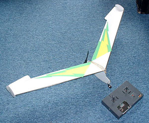
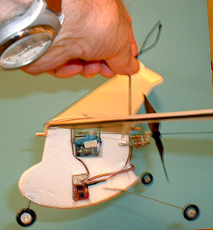
Front upper view with Plantraco transmitter shows off basic simplicity of the model structure
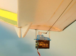
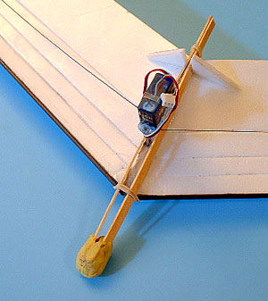
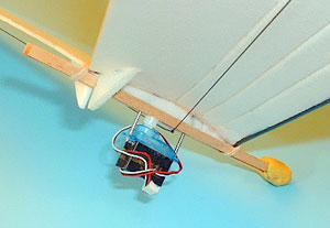
Micro servo is shown mounted to wing with long screws. Triangles brace wing against fuselage
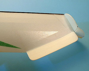
Top view of right wing tip showed fixed up elevator position and rudder angled for right turn
Wood strips with clay, held around servo with rubber bands for wing-alone CG hand glide tests
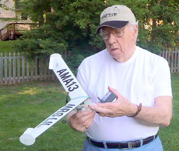
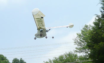
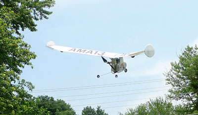
Worth ready to fly the half size foam RC version of his 66 year old free flight design from 1942
 Original size Lil Misery, built in 1989 by Joe Beshar as gift when John Worth retired from AMA.
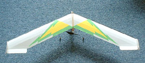
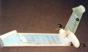
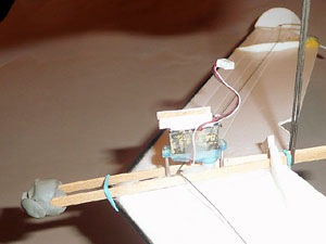
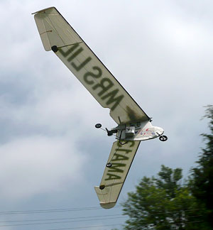
Top view of Mrs Lil showing sweptback foam wing with elevators and rudders on wing tips
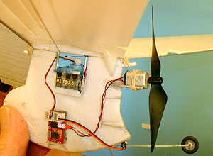
Left side shows installation of receiver, servo, motor, prop, landing gear, and wing mounting
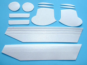
Layout of shaped sheet foam parts. 2 fuselage shapes are to be laminated for double thickness
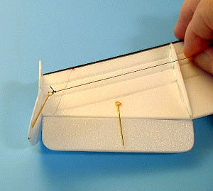
Bottom of right wing tip showing elevator, with the rudder being pulled outward by servo cord
12 Another view of temporary wood strips with clay, for determining correct model CG location
13 Complete model hanging level from cord at wing trailing edge matches wing-alone CG position
16 When wing hangs level upside down it has the right amount of clay for glide tests right side up.
For this model the neutral elevator angle is fixed at about 30 degrees of what we would normally regard as up elevator. In a model with a normal horizontal tail relatively far back from the wing the angular difference would be only a few degrees. But for this model, with the effectivetail being so close to the CG, the difference must be much greater. It should be noted that the horizontal wing control surfaces are not controllable, except for manual trimming to get the model to fly straight when gliding with motor power off or at low throttle.
The CG position is at the trailing edge of the center of the wing. Thats where the model should balance for initial hand glides. Then, depending on whether the model stalls or dives when hand launched without power, the CG is adjusted with blobs of modeling clay to produce a smooth glide pathmore clay on the nose to correct a stall, more behind the CG to correct a dive. Note: more or less up elevator can also help, but not more than a few degreesthe model needs at least 20 degrees of ˜neutral up elevator for stability. The thing to keep in mind here is that the model was designed to fly without control inputsif the radio quits working and the motor cuts, the model should glide down safely to a good landing,
Its important to get the CG right, to avoid crashing the model on initial flight attempt. A flying wing is much more critical regarding CG location than a typical model with the tail thats back much further. I use a very simple glide test arrangement to find the correct CG location. It consists of just gliding the wing assembly without the fuselage pod and its receiver, battery, and motor/prop assembly.
The wing assembly includes the servo hanging down from the center wing rib. I took a couple of hardwood strips that were 1/20 x 3/16 x 5 1/2 (any roughly similar size would be ok) and I held them under the center of the wing alongside the servo mounting rods and then secured them with rubber bands across the top of the wing and around the strips at the front and back of the wing center.
Then I took a blob of clay and put it on the front of the strips, just to get some weight forward of the wing. The simplest way to check for the correct CG position is to loop a short length of string around the strips at the trailing edge of the wing centerline, so that the wing hangs from that point. My first attempt showed the wing balanced nose high, so I added more clay up front until I got the wing to balance level. When I was satisfied with the balance, I went outside my house and tried some hand glides, using the servo as a hand hold for gentle launching.
First, however, I made sure that the elevators were set at about 30 degreesup and that the rudders were at neutral (even partially deflected outward is ok just so both rudders are the same amount away from neutral). A few hand glides showed a beautifully smooth straight ahead glide. I then tried gliding with one rudder deflected fully outward, to see the effectiveness of this drag type of control. The model glided in a nice gentle circle.
Thus I was assured that the model would be trimmed well if I achieved the same balance when I replaced the test glide strips and weight with the fuselage pod and all its components. This time the complete model hanging from the string at the rear wing dowel hung nose down, even with all components moved as far rearward as there was room for.
So I added equal blobs of clay at the trailing edge of the wing at the outboard wing ribsthis was the furthest aft I could add weight and could use the least amount of clay. Note that equal amounts of clay should be used at the two outer wing points so that lateral balance was provided as well as fore-aft balancethe model should hang level in both front and side views.
When I got the complete model to hang level, a few gentle hand glides with the completely assembled model showed that it glided as well as before. I then tried some low powered glides. These went well so I increased the power a little until the model climbed gently. I didnt go for maximum because I was happy with gentle climbs and circlesthats how the original free flight model flew and it is suited that way to indoor flying, which is what I built the model for.
SPECS:
PLANE: Mrs. Lil
TYPE: Micro indoor flying wing
WINGSPAN: 25 in.
WING AREA: 73 sq. in.
WEIGHT: 1.4 oz.
WING LOADING: 2.75 oz./sq. ft.
LENGTH: 9.5 in.
RADIO: 2 channels required; flown with a Plantraco receiver/ESC combo, 1 Blue Bird 2.7-gram sub micro servo
POWER SYSTEM: Direct drive N20-ULV motor, Plantraco 100 mm plastic prop, single cell 250mAh LiPo battery
MINIMAL FLYING AREA: Basketball gym
Construction
Now for some details as to how the model was built: the entire structure of the model is made from 2mm sheet foam. Depron would be a good choice to use because the wing airfoil shape could easily be formed by gently rolling it a few times over the rolled edge of a rounded kitchen counter top. The foam sheet I used was not Depron and was too stiff for bending in an airfoil shape, so I put several grooves in the underside of the wing so it could be bent easily without cracking.
As shown in the photo, there are three grooves in each wing panel, one at 3/8-inch from the leading edge, the second another 3/8 from the first groove, and a third 1/2-inch behind the second. Foam ribs glued to the tip of each wing panel hold the curved airfoil shape of the center rib.
A note about making the grooves: it is desired to make the grooves ˜V shaped for easy bending of the foam sheet. I used a letter opener which was very much like a dinner knife, but without a sharp blade. A sharp blade will too easily cut through the foam sheet. A blunted blade edge allows the grooves to be pressed down into the foam but not all the way through. Thus a compressedv groove is produced which allows the wing shape to be bent without breaking. Otherwise construction of this model is very ordinary, provided odorless type CA glue is used so that the foam is not melted or deformed at the glue joints.
Turn control is provided by the rudders which deflect in the outboard direction only. What is desired is a drag plate effect at the tip of wing which slows down that wing tip while the other wing tip is free to swing around more quickly to turn the model. Thus, although there are two rudders, only one is used at a time. Deflecting the right wing tip rudder to the right produces a right turn and deflecting the left rudder produces a left turn.
EQUIPMENT CHOICES
I chose the Plantraco Micro 9 receiver for this model, available in the USA from Air Midi Micros in California or BSD Micro RC in Missouri. Its a very reasonable priced receiver and it has proved to be one of the best for microflightvery light (only 0.9 gram!) and capable of operating micro servos. It also has a built-in ESC (Electronic Speed Controller). A single E-Tec 250mah Lipo battery operates the RC system, including the motor.
In this model a single 2.7 gram Plantraco Blue Arrow servo operates both rudders, one at a time depending upon whether right or left turn is desiredthe servo pulls on a control arm ahead of the rudder hinge line with a thread, so that the rudder behind that line is deflected outward. When the servo control arm moves in the opposite direction, to go to neutral or for opposite rudder control, the self-centering scotch tape rudder hinge returns the rudder to neutral.
Weighing only 40 grams, ready to fly, this model can fly gently or peppy. After trying several motor/prop combinations, the one I like best is the direct drive N20-ULV (Ultra Low Voltage) from Bob Selman Designs using a Plantraco plastic 100 mm prop. Using a direct drive motor means that it drives a small prop at high rpm for good thrust. This motor weighs 5 grams and sells for about $4.
Using a smaller motor with a gear drive and swinging a larger prop was not a good option because the larger prop would hit the wing trailing edge and there would be essentially no ground clearance for the prop tips. Thus the direct drive motor/smaller prop combination is more suitable. It operates from a single Lipo cell, but draws relatively heavy current so its needs a battery of about 250 mah capacity.
AIRBORNE
This design does best indoors, although its fine outdoors on a calm day. The tailless configuration means it is very sensitive to gusts of wind so it is best flown in smooth air and at low speed.
Incidentally, this microflight version of the old model has been renamed Mrs. Lil, a neat twist of the original name, in recognition of 58 years of marriage to my wife, Mrs. Lil flies best gently and gracefully. And flights of 10 minutes or more are possible on a single charge, or several flights of a few minutes each.
The outcome of this project indicates how the new micro light RC systems adapt well to simple models. The Plantraco components have performed well in this design and should do well in similar size and weight models.
Footnote
The author was President of the Academy of Model Aeronautics in 1963 and Executive Director from 1964 through 1980. He flew his first RC model in 1947; possibly earlier than any other current living modeler. He produces a monthly online-only internet website called RC Micro World, which can be seen at www.cloud9rc.com
Links
Air Midi Micros, www.airmidimicros.com, (775) 783-8545
Bob Selman Designs, www.bsdmicrorc.com, (417) 358-9521
Plantraco, www.plantraco.com, (306) 955-1836
