 Fly RC Magazine WE LIVE RC
 E-Flite Platinum Series
P-51B Mustang 32E
Optional Landing Gear
Instruction
By Tom Hunt
The instruction manual leaves a lot to be desired in the installation of the supplied landing gear doors to the landing gear legs. I will describe my method for attaching them. Also, the landing gear legs supplied with the retract kit do not look like the full scale aircraft struts. They are straight legs with the wheel facing inboard. The full scale aircraft had offset oleo type struts that faced the tire to the outside. Since the fixed-gear version of this kit came with more scale-like struts, I modified these struts to install on the Eflite electric retracts.
The first step is to counter bore one side of the supplied wheel hubs to get it to sit closer to the strut with a wheel collar installed on the inboard side. I removed about 1/8 inch. The next step is to re-bend the offset in the strut a little deeper. This will allow the wheel to retract fully into the well. The strut length will also need to be shortened about 3/8 inch and a flat ground on the opposite side to accept the set screw in the retract unit.
Install the unit with the new landing gear strut in the model in the retracted position with the set screws loose. Adjust the length until the wheel sits centered in the well and tighten the set screws. Add two nylon landing gear straps for 5/32 wire diameter to the landing gear legs. Tack them in place with CA, approximating the angle to be parallel with the lower wing skin. The “hump” faces the outside towards the door. Extend the gear and add a flat strap to the inside and bolt the two together with some long 2-56 machine screws. Retract gear again and make a paper template to locate the screw holes. Transfer the screw holes into the supplied landing gear doors. Carefully extend the gear without moving the door and make note of the distance between the inside of the doors and the LG straps attached to the strut. Add some nuts to all the screws that will stop the door in the proper position off the strut. Retract the gear again and adjust the position of each nut again to get the door to seat properly against the wing. Extend the gear again and tack glue the door to the nuts. Retract the gear and cut off the screw flush with the outside, or if you would like a more secure mounting, added more nuts to the outside and paint to match. I just added another layer of white trim film to the door to cover over the end of the screws. I have had a number of less than perfect landings with this new gear/door arrangement and I have yet to have a wheel get stuck in the well or lose a door!
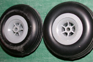
The supplied wheel must be counter-bored on one side to recess the inboard wheel collar. This is to get the wheel closer to the leg and ultimately get the wheel to fully submerge in the wheel well.
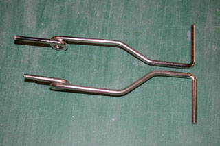 The fixed gear wire supplied with the kit needs to be modified to work with the 25-46 electric retracts. The wire must be shortened by 3/8 inch on the end that fits into the retract unit and a flat ground on the other side of the leg for the retract set screws.
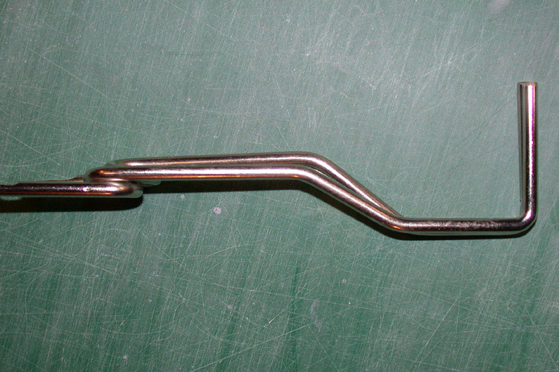
The landing gear wire offset must be deepened by about 5/32, the width of the wire, to get the wheel to fully submerge in the wheel well. The difference between the stock (top) and modified (bottom) can be seen in this picture.
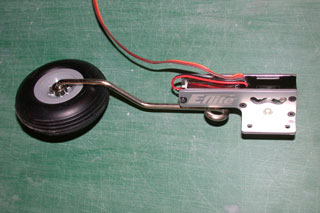
The wheel, with the new counterbore for the inboard collar and the wire are loosely assembled to the retract unit.
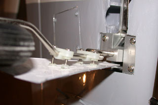
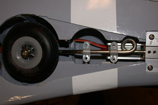 The unit is installed in the wing and the wheel centered in the well, then the set screws tightened. Hump-type 5/32 LG straps are tack glued to the struts (hump side outward).
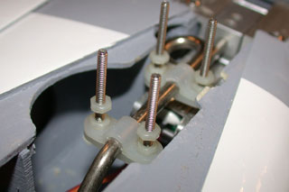
 Extend the gear. I added flat landing gear straps to the inboard side of the landing gear leg with screws that pass through the pair and added nuts to secure the assembly.
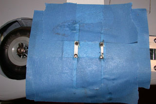
![]() Using a paper template (not shown) mark the position of the screws with the gear in the up position. Transfer the holes to the supplied gear doors.
Using a paper template (not shown) mark the position of the screws with the gear in the up position. Transfer the holes to the supplied gear doors.
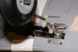
 Extend the gear and note the gap between the inside of the door and the nuts.
 Remove the door, retract the gear and add a second set of nuts on the screws that will act as stops for the gear door.
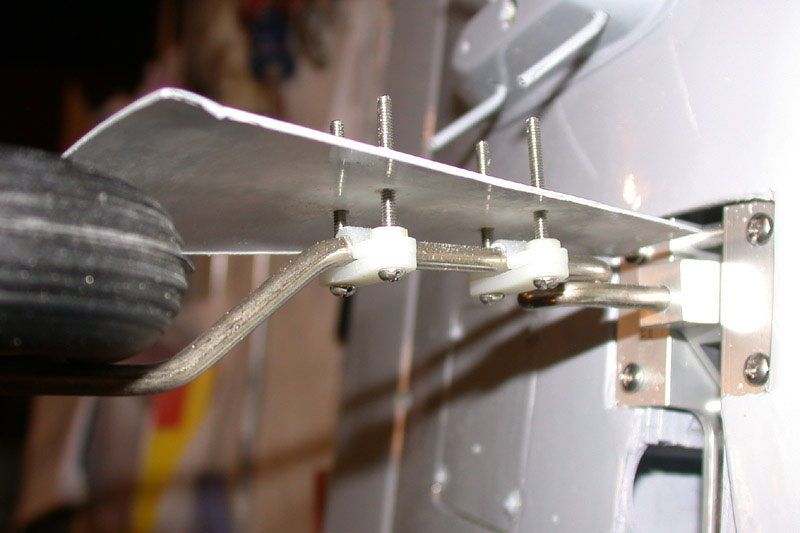
 Replace the door and adjust the second set of nuts until the door sets flush with the bottom of the wing. Tack glue the door to the nuts and cut the screws off flush with the outside. Alternately, you can add another set off nuts to the outside of the doors if you fly off very rough fields.
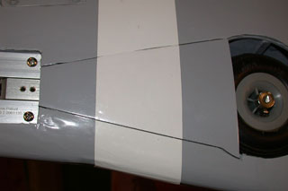 The finished installation with new white stripes added to the doors to cover the ends of the screws.
Add some more glue to the inside to be sure the nuts don’t turn and/or the doors do not come off the nuts.
