This month’s column is based on building the Stinson SR-9, blog No. 10, on rcmodel.com. For direct access to all of my blog entries on this (or any other) project, go to the archives tab partway down my home page and click the appropriate subject under categories.
It’s been a while since I have done any work that counts on this airplane, in fact, I have to confess that I’ve been letting it gather dust in my shop for about a year. I set the Stinson aside to work on the old FlyLine Great Lakes Trainer kit. That project turned into a twenty-nine-installment blog series… check the archives tab on my home page if you missed it. Just as that project ended up letting me finish it, it became clear that I needed to build a pre-production TigerKitten from the new kit my friends at Premier Balsa Kits are introducing, in order to help check out that new product for them. As you have probably figured out by now, I’m not capable of doing anything relating to model airplanes the quick way, so the Stinson spent several more months getting dusty on the back workbench.
At the point I made the last blog entry on the Stinson project I’d gotten the tail surfaces built up along with the left wing to the point of adding all the leading edge sheet and the capstrips. What was left to document was the final sanding to shape of the wing structure along with building the flap and aileron. Since building the right wing is essentially a mirror image operation, I planned to do that off-camera, intending to pick up the blog as I started work on the fuselage. All that worked out just as planned, but while I was working on those two other airplanes I had to replace my old computer. The new one works way better, but in the process of changing to a new operating system and to different image processing software, guess what happened to all those images of building the aileron and so on?
So, I shot some after-the-fact images of one fully sheeted and sanded wing along with several views of the completed ailerons and flaps to give you an idea of what that part of the structure is supposed to look like. In the event you might be using my notes as a guide to building your own SR-9, don’t worry. The kit instruction book is more than sufficient to get you through without my help. Let’s have a look at these catch-up photos. (All this stuff is covered in Stinson blog No. 9 on www.rcmodel.com)
Let’s get on with building the fuselage. In order to provide the most useful evaluation of this kit for those of you who are reading this, I’m following the construction steps in exactly the order they are presented in the instruction manual. The book says, build the tail surfaces first, then the wing panels and finally the fuselage, so that’s exactly what I’m doing. Speaking of the instruction manual, I’m going to suggest that you not even think of trying to build the fuselage without it. Unlike smaller models you may have built before, the fuselage formers on this one are not one or two complex shapes cut from appropriate pieces of sheet balsa…they are built up, most of them from over a dozen parts each, and you can’t identify the players without a program. With all that said, let’s build.
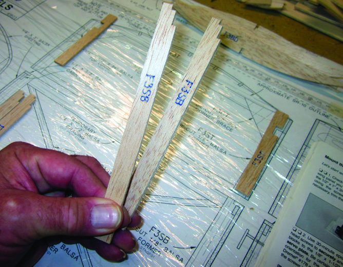
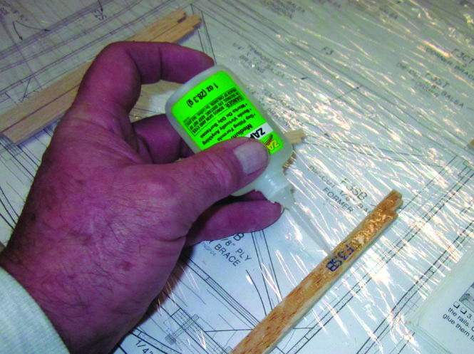
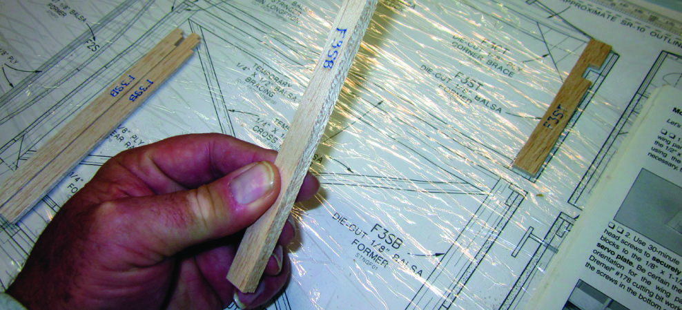
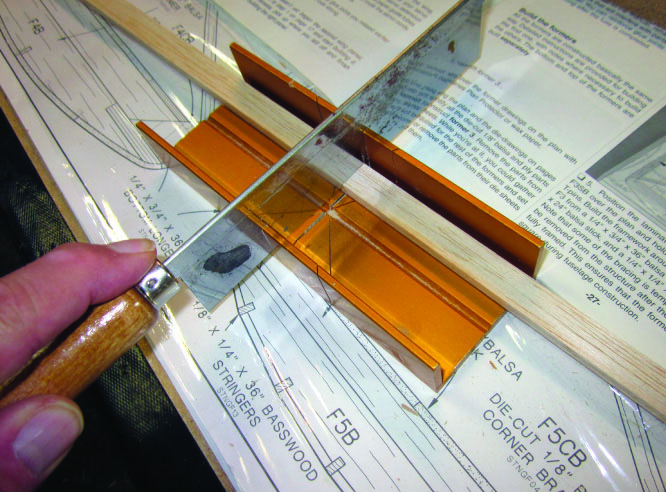
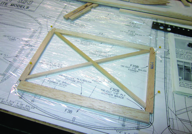
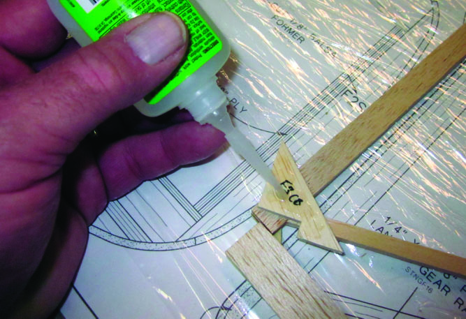
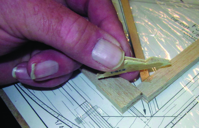
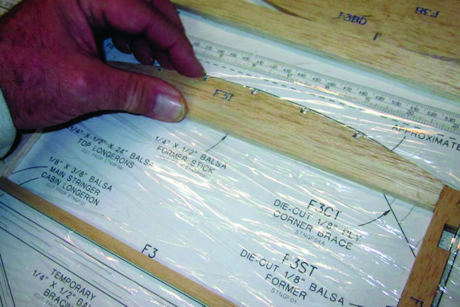
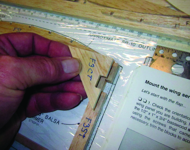
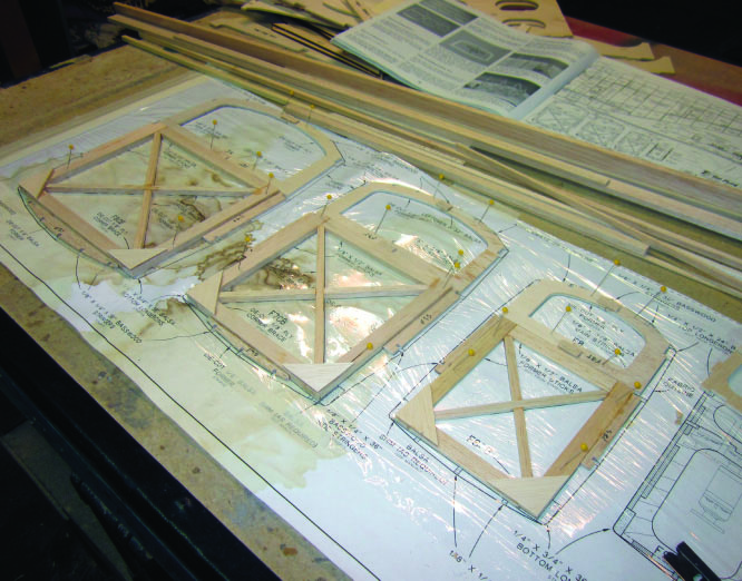
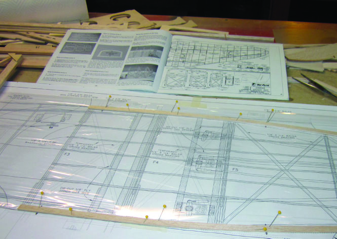
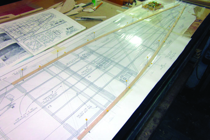
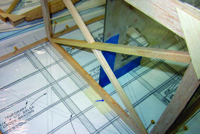
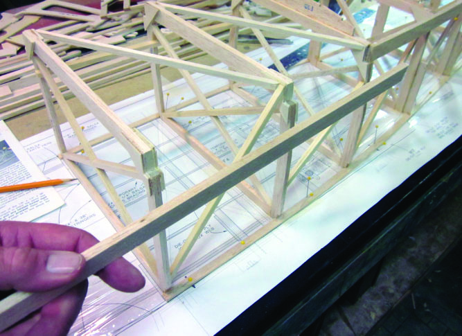
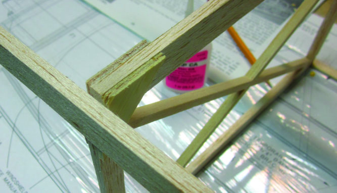
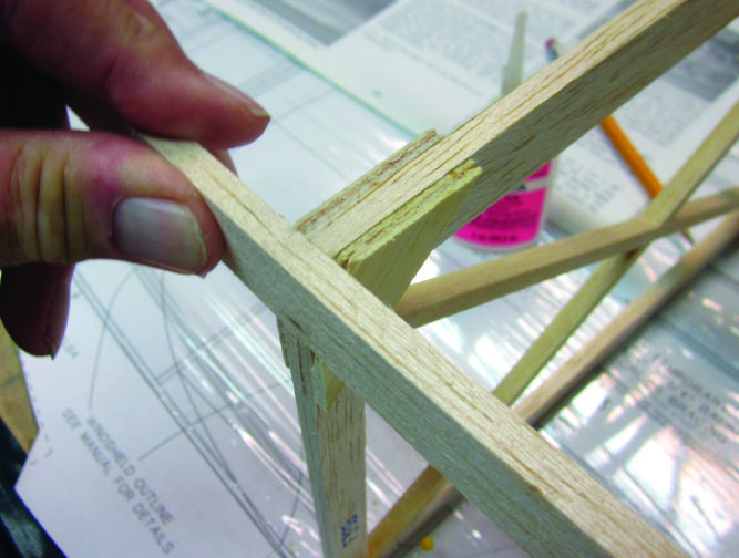
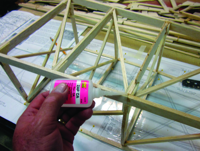
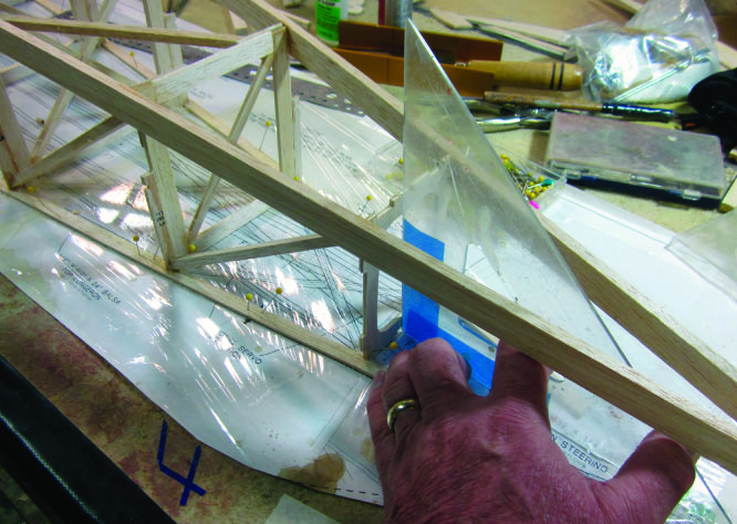
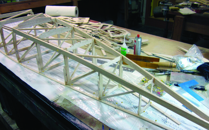
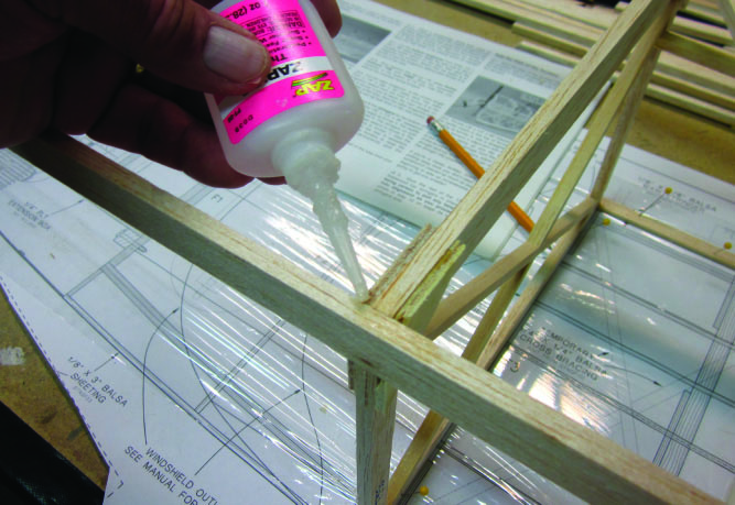
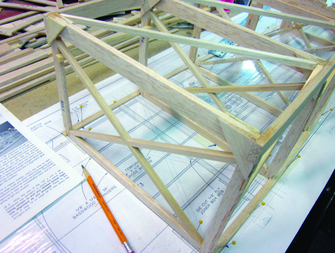
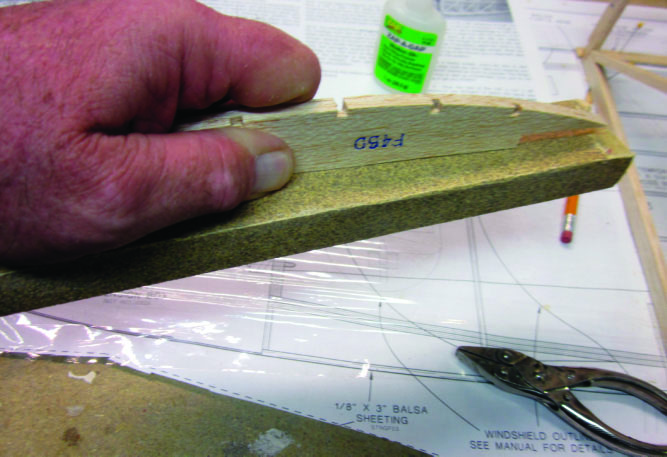
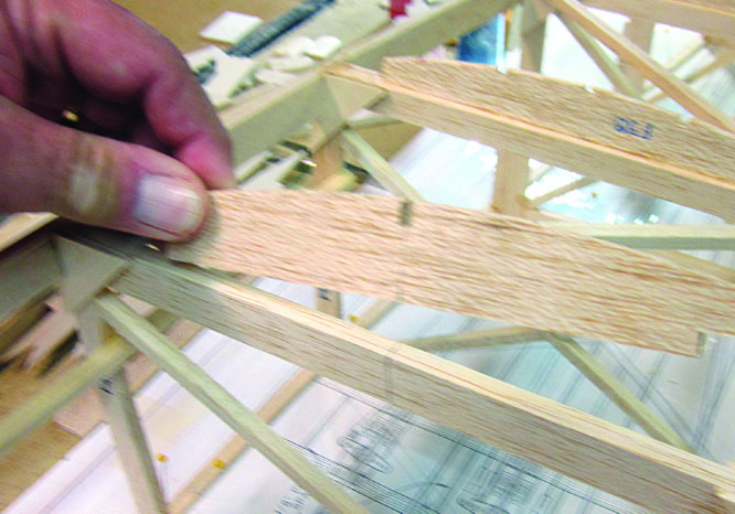
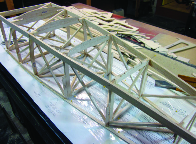
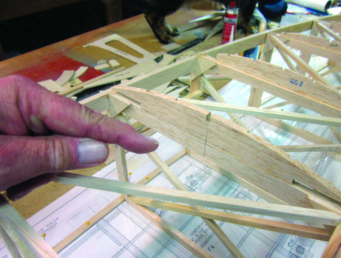
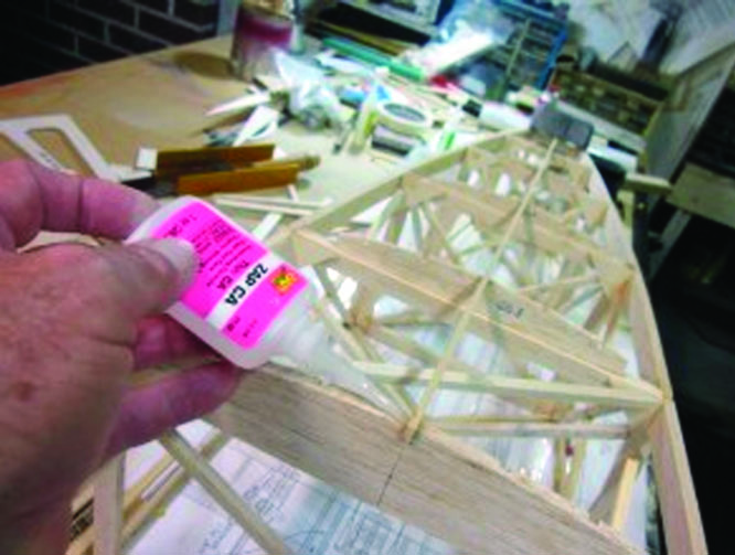
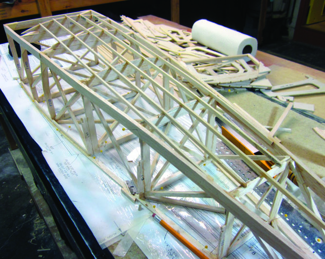
It turns out that we start by building former F-3. (I told you this was a complicated airplane.) The instructions walk you through each step of that process and then turn you loose to build F-4 through F-8 in pretty much the same way. You begin by laminating several separate pieces together to make the former sides. Here I’m holding two of the F3SB pieces that will be glued together to make a single ¼ inch thick part. You can see the two F3SB’s for the other side of the former laid out on the plan.I’m using ZAP cyanoacrylate adhesives almost exclusively on this project. Really alert readers of rcmodel.com may remember that I once explained that I preferred wood glue such as Titebond for primary construction. That was before I discovered that I have a severe contact dermatitis reaction to formaldehyde, which is a major component of Titebond and similar products. You don’t want to know how I found out. Epoxies, by the way, have pretty much the same effect, so I use latex examining gloves when I need to use them. With reasonable precautions to minimize contact and frequent handwashing the ZAP series of products do not appear to bother me. Ironic, huh? CA was supposed to be the nasty stuff. Here I’m using ZAP-A-GAP (medium viscosity) to laminate two F3SB’s. The ZAP remains wet while I spread it evenly over one of the joining surfaces.I aligned these two pieces accurately, applied moderate finger pressure for ten seconds or so, and the ZAP bonded tight. With a larger or more complex assembly I’d use clamps of one sort or another. Next I’ll do the same with all the other pieces you see waiting on the plan.Quite a few of the cross member pieces of the formers are cut from 1/4×1/2×36 inch balsa provided in the kit. This is a big enough piece of wood that even your best efforts at keeping your razor blade or No. 11 knife SQUARE to the cut might not be good enough. I have gotten into the habit of using a razor saw and miter box for jobs like. (Sorry, I don’t recall the brand name on this one.)The laminated F3SB’s I just made up go together with a 1/4 inch square and a 1/4×1/2 inch crossmember to form the basic former structure. The 1/4 inch square cross braces are temporary, they will become scrap later, but there is plenty of material provided in the kit to make them. Don’t leave them out.Lining these up is pretty much intuitive. I’ll put in another pair of braces on the other side, the part you can’t see here. The OTHER F3CB’s will go on the back of the assembly, but not yet.The bottom corner braces (F3CB) go on next. I used ZAP-A-GAP here as I usually do for open joints.F-3 is built in two separate sections, a top and a bottom. The F3ST top sides are laminated just like the ones on the bottom.There are four F3CT top corner braces, too. One goes here, another on the left, and the remaining two will go on the rear face of the assembly.Here I have F-3, F-4 and F-5 assembled in place over the plan. The shiny stuff is clear kitchen wrap to keep ZAP from sticking to the plan. The stains aren’t part of the design, I spilled my coffee. The instructions call for you to finish building formers F-3 through F-8 at this point.I began actual fuselage assembly by laying out the main stringers over the plan. These are 1/8×3/8 inch balsa strip that readily bends to conform to the required curvature.Here’s another look at the side stringers pinned in place. There are a lot of lines on the plan denoting the exact location of a lot of components—take your time, study the plan and be sure you are working on what you think you are.That goes double for positioning the F-3 through F-8 formers over the plan. Be sure you line up with the correct set of marks. This is F-4 squared up, pinned into place, and glued with ZAPThe bottom longerons are cut from 1/4×1/2×36 inch balsa strip stock, and are intended to be butt-spliced at F-5, where there is plenty of structure to reinforce the joint. Here the rear portion of the stringer is in place and I have cut the front portion to length.Places like this are where getting square, cleanfitting joints is important. Depending on a fillet of adhesive is an open invitation to structural failure. I have dressed the corner of the former square and you can see how the longeron is going to fit into place. Note that this is former F-4, not F-5 where the butt joint will be.It has got to fit LIKE THIS!Here’s the joint at F-5 getting a generous shot of thin ZAP once the fit and alignment have been double-checked as OK.F-9 is a simple die-cut part, you don’t have to build it up. I have assembled F-3 through F-8, added the bottom longerons, and now I am using a square to align F-9 for assembly behind them.This is the bottom of the fuselage from F-3 back to where the tailpost (vertical fin trailing edge) will fit later. Notice all the 1/4 inch cross and diagonal bracing that is built into the rear portion of the structure. These braces are permanent. If you build the fuselage square to this point and install them accurately, they’ll go a long way to ensuring that it stays square. As I’m sure you have already noticed, the fuselage structure has been built upside down over the plan to this stage. I followed the construction manual sequence exactly.I’m using thin ZAP to glue the front end of the bottom longeron into what is in fact going to be the lower right corner of F-3. I have trimmed and sanded everything to fit close and tight, so thin ZAP is the adhesive of choice here.I attached the bottom longeron to F-3 with an overhang of some extra 1/4×1/2 inch stock. When I was satisfied with the glue joint I used my razor saw to trim it off flush with the front face of the F3CB plywood gusset.I used one of my long sanding blocks with 80-grit production paper to true-up the joining edge of each of the belly formers in turn. This is F4SD.Each of the belly formers, F-3 through F-8, is cut from 1/8 inch balsa sheet. These are NOT AS WIDE as the 1/4 inch crossmember of the main former each one attaches to. Check the plan to be sure you have each belly former lined up foreand aft as called out by the drawing.Here you can see the belly formers at F-4 through F-8 in position.All that 1/4 inch square diagonal bracing serves a purpose. Make sure the corner joints fit so they’ll bear the design load and help keep the structure square.Next come the 1/4×1/8 inch basswood belly stringers–note that they begin at F-4 (not at F-3, that part will come later.)This is the bottom/main fuselage assembly with all the belly stringers in place, ready to come off the building board so I can turn it right side up and get to work on the top.
That’s all we have room for here, but there’s more. Go to http://www.rcmodel.com/2012/07/building-the-stinson-sr-9-10/ to see all the rest of the details of Stinson blog No. 10.
 Fly RC Magazine WE LIVE RC