 Fly RC Magazine WE LIVE RC
Build This Classic Golden Age Racer
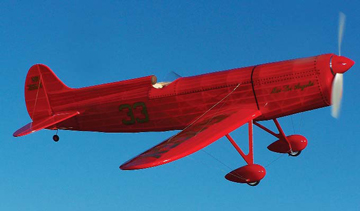
Designed in 1934 by Larry Brown and christened Miss Los Angeles, the Brown B-2 was designed around the 300hp, supercharged, 544-cubicinch Menasco Super Buccaneer engine and was the second in a series of three similar racers. The B-2 had a top speed of 270 mph and landed at 60 mph. Miss Los Angeles was a small airplane, with a wingspan of 19 feet, 3/4 inch and an overall length of 19 feet 10 inches. Gross weight was 1,299 lb. with a fuel capacity of 30 gallons. The fuselage was designed as a tight wrap-around fit for the engine and pilot, and featured a quick release upper cockpit section to aid the pilot in the event of bail out.
The structure featured traditional wood and steel construction covered with fabric. Plywood formers and spruce stringers gave the steel tube fuselage its shape, while the wings used spruce spars with plywood and spruce ribs. The B-2 used two layers of fabric on the wing leading edge rather than the plywood sheeting typical of other designs.
The Brown B-2 flew the racing circuits until the 1939 Nationals when Lee Williams flew it in the 550 cubic inch class. Williams was killed in a crash on the first lap, and Miss Los Angeles was destroyed.
THE MODEL
I designed this model using all-wood stick and tissue style construction with a 32-inch wingspan at approximately 1:7 scale. My prototype features tab and slot style wing construction to keep building as quick and simple as possible. A laser cut short kit is available to save you the trouble of cutting the numerous complex parts by hand. Plans can be downloaded or purchased at www.flyrc.com. I used Pacers thin and medium Zap CA throughout, with a few exceptions as noted. The B-2 is covered with Nelson Litefilm with custom markings by Callie Graphics.
I prefer to fly lightly-loaded models, and thus choose 2S power systems to help keep the flying weight down. As a result, a motor that performs well with two cells is a must. The Himax motor was chosen for its ability to perform nicely at lower voltages, yet still swing a large enough prop to make the required speed. Also, when using a 2S battery, the 1.5-amp BEC in the Castle ESC will comfortably drive the four servos without fear of overload causing loss of control.
Two props were test flown, the APC 8×6 SF and the GWS 9×5. Both performed very well, keeping the motor well within its efficient operating range, and still delivering good flight times using a 1320mAh battery. An APC 9×4.7 was tested too, but did not deliver adequate pitch speed to try a test flight.
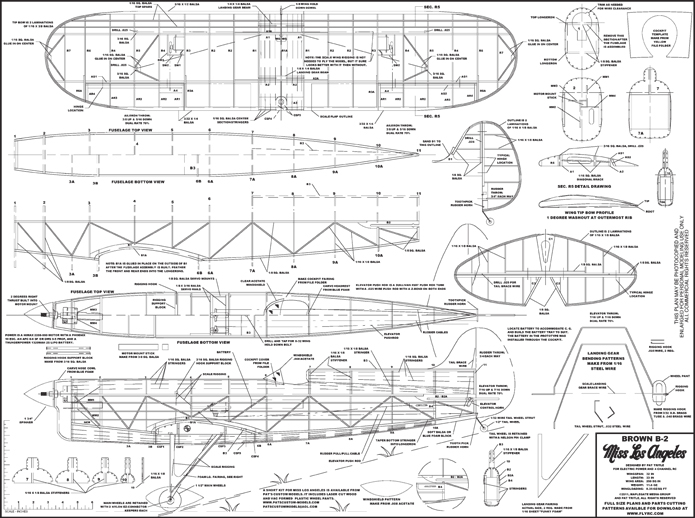
BUILDING MISS LOS ANGELES TAIL SECTION
Construction begins by forming the rudder, elevator and wingtip outlines. The bows are laminated over templates made from 3/16-inch artists foam board or cardboard using the wood sizes shown. Use thinned wood glue, letting it dry overnight before removing the bows. Clear tape applied to the templates edges skimmed with a quick coat of wax will keep the parts from sticking.
The rudder and elevator are built directly over the plans using thin and medium ZAP CA. Once the basic frames are built, remove them from the board and sand to shape. Cut strips of light CA hinge stock 5/32-inch wide and fit them into the frames, but dont glue them in until the frames have been covered.
WING ASSEMBLY
The wings also build directly over the plans with CA. Start by assembling the main and rear spars. Align and glue the front spars, A1, in place on A1A. The rear spars, A2, are glued in place on A2A, followed by the aileron spars, AS1.
Pin the spar assemblies, A3, the leading and trailing edges, and landing gear beams over the plans. Place a support block under the spars at the tips to prevent accidentally breaking the elevated spars. Fit and glue ribs R1 and R1a in place.
Unpin the assembly from the board, rock the wing to one side and pin the front spar over the plan. Due to the dihedral angle built into the spars, the wing must be built one panel at a time. Using a couple of ribs to insure proper alignment, pin the rear spar in place. Glue R3A to R3, and R6A to R6, then, glue all the ribs in place. Fit and glue the leading and trailing edges in place followed by the tip bow.
Assemble the aileron in place on the wing and glue the assembly together. Next add the servo tray, rigging blocks, diagonal bracing and 1/16-square top spars to complete the basic wing panel assembly. When the glue has dried, rock the wing over to the other panel and pin the spars to the plan. Block up the opposite tip and build the second wing the same as the first.
Remove the wing assembly from the board and sand to shape. Cut the ailerons free from the wing and do the final shaping. Cut strips of CA hinges 5/32-inch wide and fit into the ailerons.
Bend the landing gear to shape and tape it in place on the wing. Solder the front and rear struts together. Lash the assembly to the wing with heavy sewing thread and secure with thin CA.
FUSELAGE ASSEMBLY
Begin by building the two side frames directly over the plans. Leave the second side frame pinned to the board to begin joining the frames.
To join the frames, glue formers 4, 5, and 6 to the upper longeron, and former 3B, 6A, and 6B in place on B1 and the bottom longeron. Use triangles to insure the formers are glued on square. Glue the second side frame in place atop the formers, again using the triangles to insure the assembly stays square.
Remove the fuselage from the building board and glue the remaining formers and B3 in place, except 1, 2, and 3A. Fit the wing into the saddle and drill the hole in the leading edge for the hold down dowel. Remove the wing and add formers 1, 2, and 3A. Build up the motor mount using the 3/8-inch square hard balsa mount stick and the alignment gussets. Be sure to orient the gussets to prop-erly build in right thrust. Glue the mount in place, followed by the servo rails and mount beams. Glue B1A in place on B1, and B2A in place on B2, followed by 1/16 square and 1/16×1/8 balsa stringers. Glue B4 in place on the left side of the fuselage, and B3 in place flush with the wing saddle.
Carve the blue foam nose and tail blocks to shape. Carefully locate NCR on the basic nose block as this dictates final alignment and helps to shape the nose block. Hollow the block to about a 1/8-inch thick wall. Glue the tail block in place, but dont mount the nose block until final assembly.
INSTALLING THE RUNNING GEAR
Mount the servos in the fuselage and wings as shown on the plans. The aileron servos are glued in place with silicone. Run in the elevator push rod and secure at the front and rear, and at least two points in between using B4 and the PRS stand-offs. Fit the rudder assembly onto the fuselage and run in the rudder cables. Mark the exact location where the cables exit the fuselage on the plans for reference in final assembly. Run the aileron servo Y-harness, or extension leads if you plan to mix electronic differential, into the wings and secure the exit points using the WG parts.
Glue the wing hold down dowel into the wing. Align the wing onto the fuselage and drill a 9/64-inch hole in B3. Remove the wing and harden the wood with thin CA. Tap the hole for the 8-32 wing hold down bolt, harden it again and then use the tap to clean the glue residue from the threads. And with that, the model is pretty nearly finished. After a good pass of detail sanding it will be ready to cover. At this point, the belly pan has not yet been assembled on the wing. Dont frame it until the bottom of the wing has been covered.
Wire up the motor and ESC and test for proper rotation. Mount the motor and make the small relief for the wiring in Former 1 as required. Connect the receiver and make sure everything is working properly while the systems are still accessible. Now the cockpit opening can be cut from yellow file folder using the provided pattern and glued in place.
COVERING THE MODEL
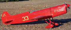
I used Nelson Litefilm to cover the B-2. Litefilm is also available as Microlite from Tower Hobbies. Tissue or silkspan and dope can also be used by the more adventurous types. Begin by covering the bottom outer wing panels. Dont cover the center section. Bolt the wing onto the fuselage and build up the belly pan, then cover it starting at ribs R1 and work toward the centerline stringer. Now the rest of the model can be covered. The wheel pants are built up and painted along with the nose block and landing gear assembly.
FINAL ASSEMBLY
Glue the rudder, elevator, and aileron hinges in place using Pacer Formula 560 Canopy Glue. Bolt the wing in place and use it as reference to align the vertical and horizontal stabilizers. Once all is nicely aligned, glue the stabilizers in place.
Mount the main wheels using Du-Bros nylon EZ-Connector keepers. If you plan to add the scale flying wires and tail brace, make up the upper retention hooks from .032 wire, and lowers from 3/32 O. D. brass tubing and .040 brass wire. Tie the spreader wire between the land- ing gear and secure with thin CA. Center the wheels inside the pants and glue them in place. Retain the tail wheel using a Nelson Pin Clamp or EZ-Connector keeper on each side of the wheel. Add the rigging if so desired. On the prototype I used 10-poundtest fishing swivels on the upper retention hooks, and secured the wires with a 1/8-long crimp made from 1/16 O. D. aluminum tubing.
Glue the nose block in place and mount the prop and spinner. Cut the windshield from .008-inch acetate and form it by taping it securely near the bottom of a three-inch diameter glass jar. Fill the jar with water to just above the windshield and place it in a microwave oven on high until the water almost boils. Let the jar cool, then remove the formed windshield and glue it in place.
Balance the model 2 3/16 inches back from the wing leading edge. Locate the battery to set the C. G. and make the mount plate accordingly. Set the control throws as shown on the plans, and with that, the model is ready to fly.
AIRBORNE
Before flying Miss Los Angeles for the first time, double check that the controls are moving, and are moving in the right direction. Right after take-off is a real bad time to find out something isnt right. Load a freshly charged battery and double check the balance as well. If everything is working properly, its time to fly.
The B-2 is not outrageously fast with the recommended power system, but has a nice scale look at full speed. The model is quite sensitive on the ailerons and elevator, so keep the control inputs smooth and deliberate. With the aileron low rate the roll is manageable, and the model turns very well at speed, but youll need to go back to high rates for landing or risk running out of aileron authority at the lower speed on your approach. Rudder control is docile yet very positive throughout the speed range, and offers no coupling in either pitch or roll. And finally, ground handling on both take-off and landing is excellent in spite of the high angle of attack in the 3-point attitude.
To take off, set the rates on full and advance the throttle to full power and let the tail come up. Once flying speed is reached, a touch of elevator is all youll need. Climb to a safe altitude and trim for level flight. If the model seems overly sensitive, turn the rates down. With the setup shown on the plans, I find the B-2 to be very manageable on high rates, but must be flown with a light touch.
When flying the course, the B-2 likes a fairly steep bank, and needs a good bit of elevator through the turn. The roll into and out of the turn is crisp and quick and once you learn how the controls respond its really easy to maintain a good line.
 Landing is really fun. To start the descent, reduce the power to about 80% and turn the rates back up to full. The model slows down very well, but the ailerons do get a bit lazy at lower speeds. Fly the final approach leg with a bit of power and the nose up just a bit. Use the elevator to maintain angle of attack, and power to control the rate of sink. The rudder has plenty of authority in maintaining a good line on your approach. As the airplane gets close to the ground, reduce the power and ease the nose up and shell float right on for a perfect three-point touchdown.
SPECS
PLANE: Brown B-2 Miss Los Angeles
TYPE: Golden Age park flyer
FOR: Intermediate builders and pilots
WINGSPAN: 32 in.
WING AREA: 200 sq. in.
FLYING WEIGHT: 11.6 oz.
WING LOADING: 8.35 oz./sq. ft.
WING CUBE LOADING: 7.1
LENGTH: 33 in.
RADIO: 4 channels required; flown with a Spektrum DX6 transmitter, Spektrum AR6000 receiver, 4 Dymond D-47 sub-micro servos
POWER SYSTEM: Himax 2808-890 brushless outrunner, APC 8×6 SF prop, Castle Creations Phoenix 10 ESC, Thunder Power 2S 1320mAh LiPo battery
FULL THROTTLE POWER: 5.5 amps, 43 watts, 3.7 W/oz., 59.6 W/lb.
TOP RPM: 5,800
DURATION: 12-15 minutes
MINIMAL FLYING AREA: Ball field
COMPONENTS NEEDED TO COMPLETE: 40-75 watt brushless motor, 10-amp speed control, prop, 4-channel radio with sub-micro servos
 SPEC SUMMARY: The Brown B-2 Miss Los Angeles is a classic and colorful Golden Age racer that will surely turn heads whenever you fly it. This model features traditional stick construction blended with modern design and optional laser cut parts for faster and more accurate building. Once done, its compact size and light weight will let you race in any convenient park or schoolyard.
PLANS, PARTS AND MARKINGS
If you want to build your own Miss Los Angeles, full size, tiled plans, with all the parts shown are available for free download at www.flyrc.com. You can also order single sheet plans there as well. A laser-cut short kit including 5 balsa and 2 plywood sheets along with plastic wheel pants is available from Pats Custom Models. You will need to supply your own sheet and stick stock, as well as wire and hardware. The vinyl markings package available from Callie Graphics includes the 2-color wing and tail numbers, race numbers and Miss Los Angeles script for the cowl.
CONCLUSION
And thats about all there is to it. Miss Los Angeles is a fun model to build and also flies very nicely. Lets go racing!
Links
APC Propellers, dist. Landing Products, www.apcprop.com , (530) 661-0399
Callie Graphics, www.callie-graphics.com , (505) 293-2922
Castle Creations, www.castlecreations.com , (913) 390-6939
Du-Bro, www.dubro.com , (800) 848-9411
Formula 560 is manufactured by Pacer Technology, www.zapglue.com
Himax Motors, dist. by Maxx Products International, Inc., www.maxxprod.com , (847) 438-2233
Nelson LiteFilm, dist. by Nelson Hobbies, www.nelsonhobby.com , (503) 806-3785
Pats Custom Models, www.patscustommodels.com , (505) 296-4511
Spektrum, dist. by Horizon Hobby, www.spektrumrc.com , (800) 338-4639
Thunder Power RC, www.thunderpowerrc.com , (702) 228-8883
ZAP is manufactured by Pacer Technology, www.zapglue.com
