 Fly RC Magazine WE LIVE RC
The Tips And Tricks You Need To Know!
Anderson Powerpoles are among the safest, most reliable and most useful of all connectors for electric- powered airplanes. They are easy to disconnect (you wont damage your plane pulling them apart), expose no live metal contacts and do not require soldering.
Here, we will discuss additional key installation tips and tricks that, until now, have been known only to the experts. Powerpoles can convey current bursts of up to 100+ amps and can be run continuously at currents of up to 60 amps if well assembled. Review the following photos and read the captions carefully, and you will enjoy safer, more efficient electric flight while saving many hours of workbench time each year.
| 1 | 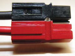 |
Tongue-and-groove dovetailing in the connector housings allows the cases to be connected snugly to each other. |
| 2 | 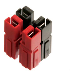 |
Housings can be joined with contacts rotated in different directions to ensure plug incompatibility. |
| 3 | 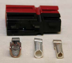 |
Three contact sizes are intended for use with different wire gauges. The sizes are officially named for applications in building construction that assume 110 volts, so dont be misled by the names. Left to right: The 45 amp pin (#261G2) is for 1014 gauge wire; the 30 amp pin (#1331) is for 1216 gauge wire; and the 15 amp pin (#1332) is for 1620 gauge wire. Once installed in connector housings, these different size pins snap together perfectly on the contact side. |
| 4 | 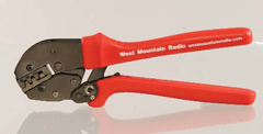 |
The PWRcrimp Crimp Tool, offered at:www.westmountainradio.com
for $49.95, crimps all three sizes of pins. |
| 5 | 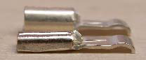 |
The contact in the foreground has been crimped. The spoon component of the contact extends in a straight line; this angle must be maintained for proper mounting of the housing. If they are bent slightly upward they may not stay in the housing; bent down they do not mate with full force. |
| 6 | 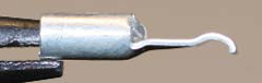 |
Close-up of a 30 amp pin before crimping. |
| 7 | 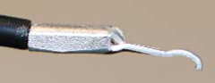 |
This pin has been crimped; notice that the contact portion has been bent slightly downward in the crimping process. A slight downward or upward bend can occur depending on the wire size you are using for a given pin. This is normalthe secret is to bend the pin back to align it parallel with the crimped part (see next photo). |
| 8 | 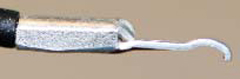 |
The crimped pin has been bent straight by hand. This will ensure proper mounting in the housing, which in turn will ensure the right pin float in the connector housing, and that, in turn, provides the best connector connection. |
| 9 | 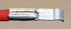  |
Detail views of a properly crimped pin. |
| 10 | 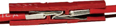 |
Cutaway view shows steel springs that hold the contacts in place. The contact portion of the pins must be straight (not bent) for proper locking of the connectors. When you mount the pin in the housing, push the pin in by hand or with the help of a small screwdriver till you hear it click as the pin snaps in place over the spring. If you feel a few thousandths play side-to-side and about 1/32-in. when you jiggle the wire, youve done it exactly right: that is pin float and it will enable the pin to seat perfectly. You will hear a crisp snap when a properly assembled connector is connected to another Powerpole. Its good for 10,000 connects and disconnects! |
| 11 | 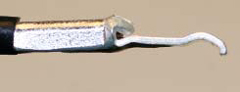 |
Note that the end of the crimped portion has slightly bunched up. This is not a properly crimped pin. |
| 12 | 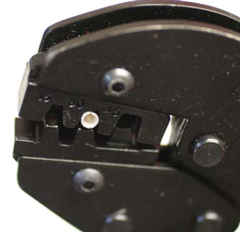 |
To avoid a bunched crimp, which occurs when the pin is placed too deeply in the die cavity, mount the pin flush with the exterior face of the crimp jaw and apply just enough pressure to hold the pin, and then insert the wire and crimp. Shown is a 30 amp pin. The 45 amp pin die on the right (see arrow) is slightly recessed: when crimping a 45 amp pin, its base should be flush with the recessed exterior surface of the die. Before crimping a 45 amp pin, bend the ears on the end slightly together by hand to ensure proper folding in the crimper. |
| 13 | 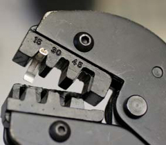 |
If a pin sticks in the upper seat of the crimping jaw and you open the crimper fully, the die cavity will bend the front of the pin down, as shown, which will likely ruin the pin. |
| 14 | 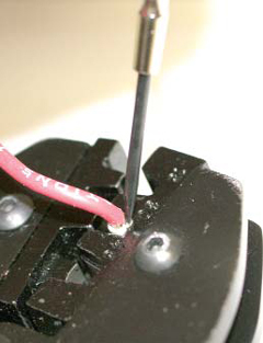 |
Be careful when opening the jaws to ensure that the contact is not stuck in the top die. If it is, stop opening the handle and push the contact out with a small screwdriver as shown. Tap it with a pair of pliers or small hammer, and the pin will fall free and the crimper will open on its own. Factors that can contribute to pin-sticking include the type of wire, condition of the dies, handle release tension and the contacts themselves. Keep the dies clean by rubbing the inside of the die with steel wool or Scotch-Brite to minimize sticking, or contact West Mountain Radio for assistance regarding stick pins. |
| 15 | 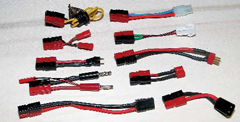 |
You are already using other connector types? No worries, you can quickly and easily make patch cords to ensure cross compatibility for all your electric flight options. You can easily make parallel circuit patch cords (for flying with 2P lithium setups), and you can easily connect two batteries in series using Powerpoles. Few connector systems offer the ease of use of Anderson Powerpoles. To order a crimper, connectors, pins and housings, contact West Mountain Radio. |
Links
West Mountain Radio, www.westmountainradio.com , (203) 853-8080
