| Simple Reliability |
ITEM LIST
Du-Bro
112 2-56 solder Kwik-Links
122 2-56 nylon Kwik-Links
172 2-56 threaded rod |
|
| Several of the planes that you have in the air, on the bench and in your shop are probably ARFs (look around!). Most of these came with nice hardware packages, but the hardware can often be improved to provide better function and/or reliability. One of the simplest areas of improvement is in the aileron linkage. While building my E-flite 25-size J3 Cub, I noticed that the aileron linkages are connected to the servo horns with snap-on EZ-link connectors. Although these are reliable, I wanted something more solid, since I intended to use the Cub for float flying. After a quick trip to the hobby shop, I was ready to improve my aileron control linkages. If you plan to build linkages such as the ones I describe in this article, do it before you install the control horns; you’ll see why as you read through the process. |
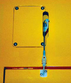
| STEP1 |
The stock linkages are plenty durable for most situations, but there’s room for failure if a snap-on EZ connector is somehow detached from the control rod. Remove the EZ connector and disconnect the clevis from the control horn. |
 |
|
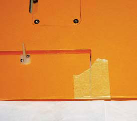
| STEP2 |
With the linkage removed, use a piece of masking tape to keep the control surface you’re working with centered. I show the aileron control surface. |
 |
|
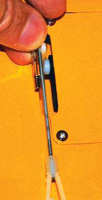
| STEP3 |
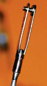
You can probably keep the stock nylon clevis that came with your aircraft and cut the control rod to length. Here, I’ve positioned a new Du-Bro nylon clevis on the threaded end of a Du-Bro 2-56 threaded rod. I installed a solder-style Du-Bro Kwik-Link next to the servo horn to determine how long the control rod should be; be sure to center the control surface and tape it into place before you make your mark. When you’ve determined its proper length, mark the rod with a fine-point permanent-ink marker, and cut it to length with a Dremel tool or something similar. The rod should be long enough to protrude through the far end of the clevis’s shank. |
 |
|
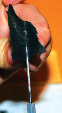
| STEP4 |
Having cut the rod to length, roughen its surface with sandpaper to give the solder a surface that’s easier to stick to than the original smooth, and often oily, stock rod. Scuff the area, clean it with alcohol and let it dry. |
 |
|
| STEP5 |
Solder a Kwik-Link in place. Follow the soldering steps given in the October issue of Fly RC, and everything should go smoothly. Let the solder cool, and then give the linkage a strong tug to make sure that the clevis is secure and that you don’t have a weak “cold” solder joint (if it isn’t shiny, start again). |
 |
|
| STEP6 |
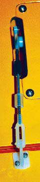
Before you install your new linkage, be sure to install the retainers for each of the Kwik-Links. At the beginning of this article, I said that if you plan to install this type of linkage, you should do so before you install the control horns. Remember that? Here’s why: notice how the linkage is no longer perpendicular to the control surface’s hinge line. I ended up moving the control horn to correct the linkage geometry. |
 |
|
CONCLUSION
Although the stock linkages on today’s ARFs are likely durable enough to suit most needs, the reliability of soldered Kwik-Links just can’t be beat. If you plan to use this type of Kwik-Link on your new ARF, keep in mind that you should position the control horns so that the linkage is properly located in relation to the servo horn. |
Links
Du-Bro www.dubro.com (800) 848-9411
|
 Fly RC Magazine WE LIVE RC
