 Fly RC Magazine WE LIVE RC
Author:
Jim Onorato
Photographers:
Walter Sidas & Jim Onorato
A Page out of the golden age of air racing
NEED TO KNOW
MANUFACTURER: ECOMRC
DISTRIBUTOR: Troy Built Models
TYPE: Sport scale racer ARF
FOR: Intermediate sport pilots
PRICE: $129.95
INTRO
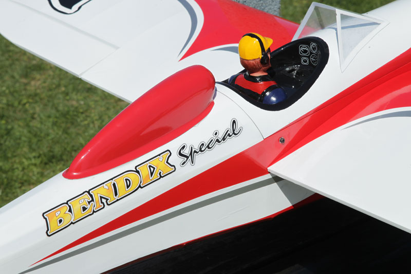
The TBM Bendix Special is one of the coolest looking sport planes I have seen in a long time. Its colorful trim scheme and unique, retro look of the 1930s gives it a lot of eye appeal. I was very pleased with this plane and was anxious to get it airborne as soon as it was assembled. I was not disappointed as it flew superbly without any bad tendencies. Two things I would suggest to improve the product would be the inclusion of a spinner and the addition of radio installation instructions.
ASSEMBLY
Since all of the fasteners are metric, you will need several small metric hex wrenches, nut drivers and metric drill bits of the sizes spelled out in the instructions. #1 and #2 Phillips screw drivers, a crimping tool and blue thread lock will also be required before you begin assembly. The 12-page instruction manual consists of numerous drawings but very little text. However, if you are contemplating building and flying this ARF, you are probably not a beginner and should have no problem assembling the Bendix since there is nothing new or tricky involved in its assembly.
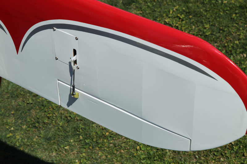
Assembly begins with the installation of the ailerons and aileron servos. CA type hinges are already installed on all control surfaces but have to be glued. All you have to do is be certain they are centered and apply a few drops of thin CA to each. The aileron servos mount to servo hatches that have the servo mounts already installed. Fiberglass control horns get epoxied into pre-cut slots in the ailerons and connect to the servos with short metal pushrods and ball links. I used snapper keepers at the servo end rather than the wheel collar shown in the instructions. The wing panels slide onto a carbon fiber wing joiner and are held in place with two socket head bolts that thread into blind nuts from the inside of the fuselage sides. Anti-rotation pins have to be glued into the panels at the root but the wing joiner does not get glued as indicated in the instruction manual.
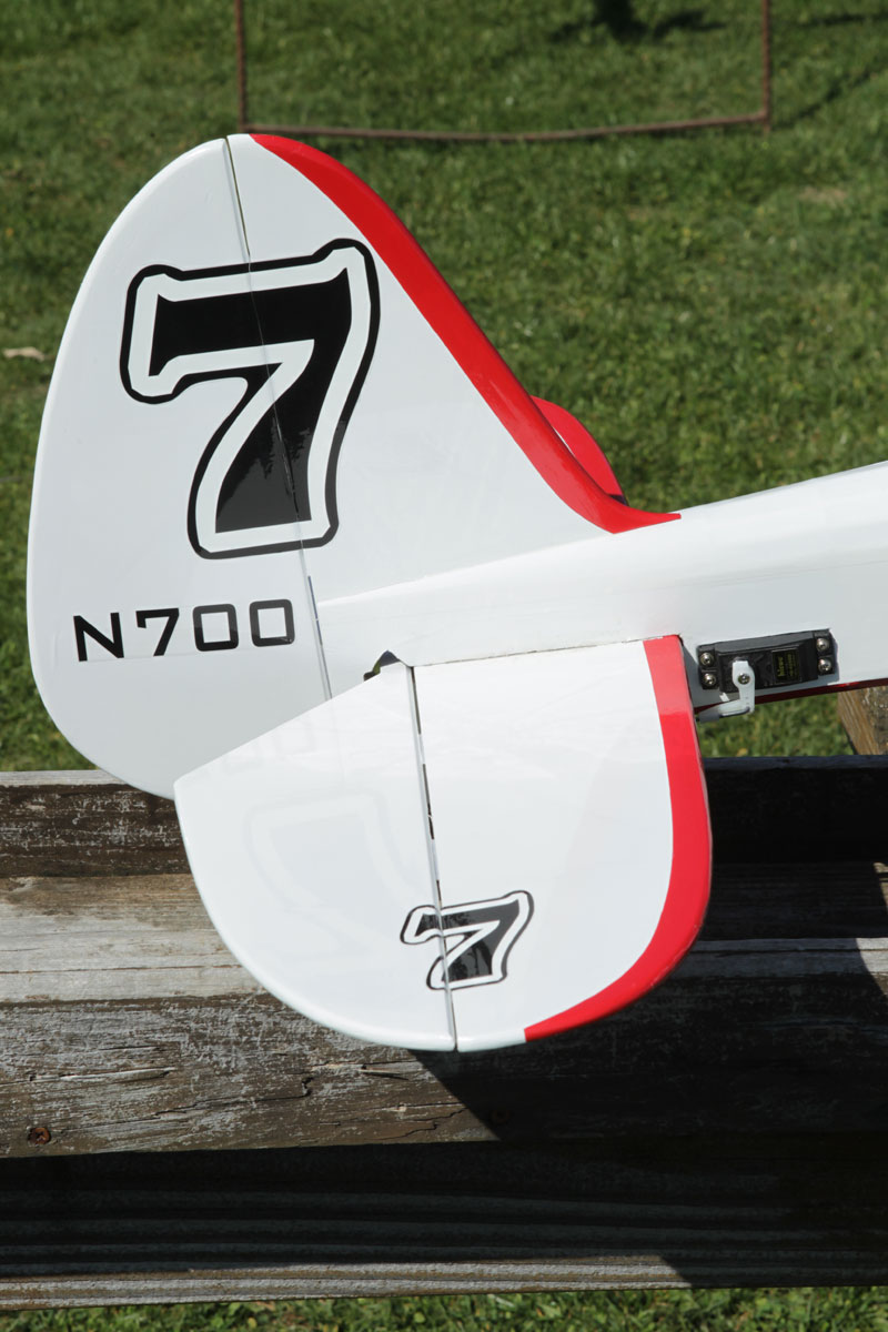
The Bendix has a one piece elevator that you slide into the slot in the fuselage followed by the stab and fin which you then epoxy in place. Be sure to remove the covering from the areas where epoxy will be applied. Finally, install the tail wheel assembly, center the hinges on the rudder and elevator and apply a few drops of thin CA to each one. The rudder and elevator servos are located in the rear of the fuselage and get connected to the control surfaces with short metal pushrods and ball links. Again, I used snapper keepers on the servo end rather than the wheel collars shown in the instructions. Slots for the fiberglass control horns are already cut in the elevator and rudder. The tail wheel is driven by the rudder and gets attached to the bottom of the fuse with three sheet metal screws through an aluminum mounting plate.
The two-piece composite engine mount provided gets attached to the firewall with four 4mm bolts. I used an O.S. FS-70 four-stroke engine and mounted it with the cylinder head at “8 o’clock” which placed the stock muffler right in the tunnel built into the underside of the fuse. This also placed the glow plug in an exposed position that made it easy to attach a Ni-Starter for starting. I lined the tunnel with adhesive- backed aluminum foil to help fuel proof the area and dissipate heat A Hitec HS-422 servo was used for the throttle and was installed on the servo tray located behind the fuel tank. The 1/16 inch throttle pushrod was connected to the engine with a ball link and to the servo with a brass pushrod connector. I assembled the fuel tank with a third line for filling and ran it through a fuel dot located in the right side of the fuse behind the cowl.
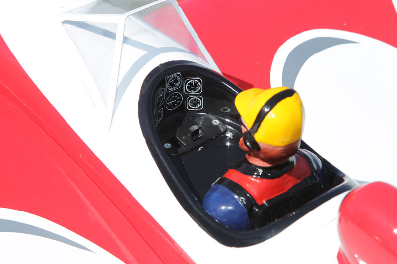
A JR charge switch for the radio was mounted in the floor of the cockpit between the pilot figure and the wind screen. The receiver battery was attached to the servo tray next to the throttle servo with hook and loop tape. I installed a plywood tray to the rear of the servo tray and attached the receiver with hook and loop tape. The satellite receiver was attached to the side of the fuse with double-sided tape.
The instructions show a two-piece landing gear but my kit had a one piece gear that I attached to the fuse with four bolts into pre-installed blind nuts. The painted landing gear fairings add a nice touch and were glued in place with PCM adhesive. I thought the wheels provided might be too small for use on our grass runway and, since the wheel pants were large enough, I replaced the 55mm wheels with 65mm wheels I found in my spare parts inventory. The wheel pants come with plywood mounting plates inside but mine were positioned too high in the pant to capture the axel and mounting screw so I added a new plate positioned flush with the bottom edge of the pant.
The pvc top hatch attaches to the fuse with tabs in the front and two bolts in the rear. If you are using electric power you may want to get rid of the bolts and install magnets to make the hatch much easier to remove to get access to the motor battery.
The remaining steps include application of the decals and installation of the windscreen, headrest and cowl which is attached with several small screws. Finally, I added a Hangar 9 pilot figure to give the Bendix that completed look.
 |
 |
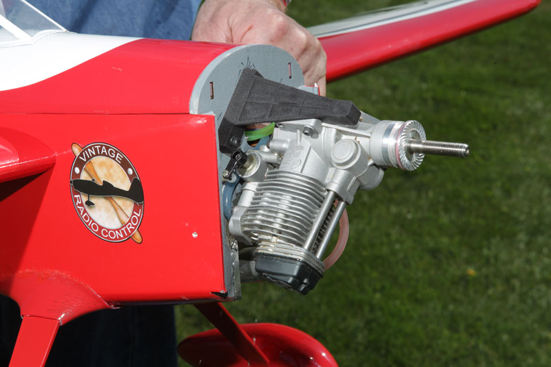 |
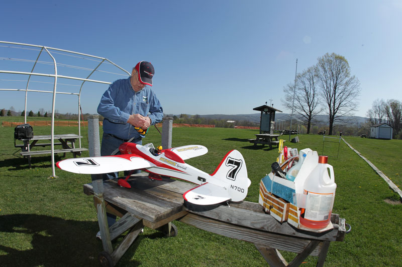
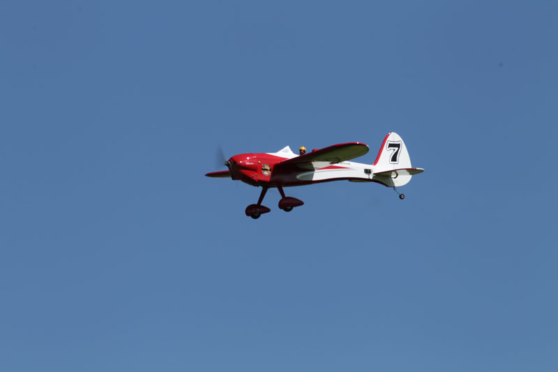
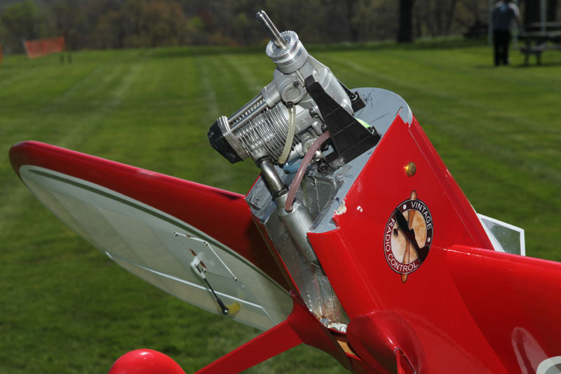
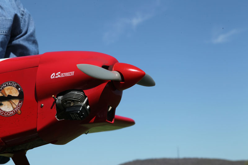
| Getting ready in the pit area – It’s a great day for flying! | Coming in for a landing… | The OS Engine mounts at an angle to properly align the exhaust. |
 |
 |
 |
| The exhaust aligns perfectly in the tunnel under the fuselage. | The aileron servos are hidden in the wing via a removable hatch. | The hatch cover is held in place with two Allen screws. Love the logo graphics! |
 |
 |
 |
| The servo for the elevator is installed in the tail. The horizontal stab slides through the fuselage and is glued in place. | Nice detailed pilot. I mounted the receiver switch/charge jack in the cockpit for easy access. | The cowl has to be cutout to allow clearance for the engine. |
