 Fly RC Magazine WE LIVE RC
Quarter-Scale
Civilian ARF
Photos By Andrew Griffith
AT A GLANCE
MANUFACTURER/DISTRIBUTOR: RCGuys.com
TYPE: Civilian giant-scale ARF
FOR: Intermediate sport pilots
MINIMUM FLYING AREA: RC Club Field
PRICE: $539
NEEDED TO COMPLETE:
Eight high-torque standard-size servos, 5-channel radio system, 35-50cc gasoline engine (or 1.60 2-stroke or 2.20 4-stroke engine), three 24-inch servo extensions, two 6-inch servo extensions and 3 Y-harnesses.
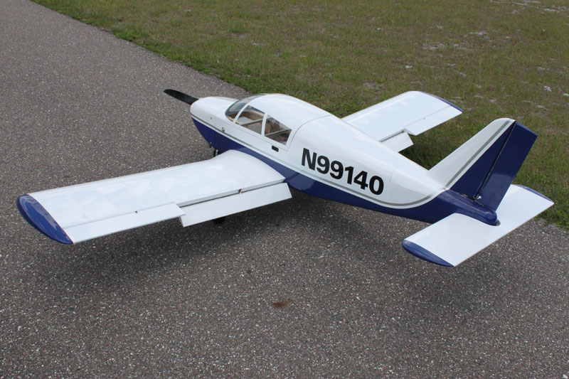
I have really enjoyed flying the RC Guys Decathlon that a friend of mine built so I was excited to get started on their Cherokee PA-140 ARF.
FIRST LOOK:
The first step of assembling any model should be to read the instruction manual from cover to cover. The assembly manual for the Cherokee is only available online, there is no printed manual included with the kit.
Download the RC Guys Cherokee 140 manual here
The manual is good but there are some details that keep it from being outstanding. The manual looks to have been developed using a prototype and some things appear to have changed with the production kit. There are some steps that are called for in the manual, like cutting the covering to make holes for the servo covers in the wings that comes already done from the factory. Also some of the parts shown in the assembly photographs, especially in the first step, differ from what is included in the production kit. I noted that during the wing servo installation the aileron servo was pictured but the mounting direction for the flap servo was neither described nor illustrated. No matter how good a product is, it’s only as good as the support you can get for it. When I contacted the manufacturer they were quick to respond to my email about the flap servo and included a picture of the proper orientation. Finally, and most importantly, there is no center of gravity indicated or discussed in the manual.
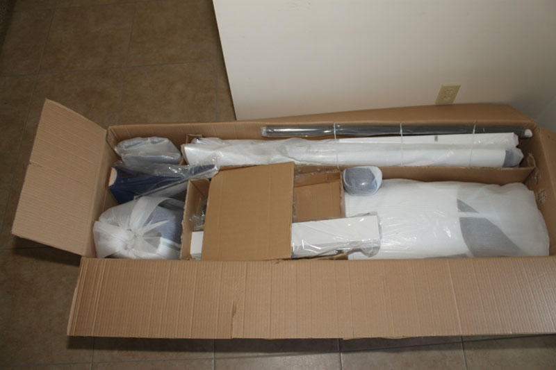
The outside of the shipping container actually ended up a little scary looking when it arrived at my door, but the packaging job of the contents was outstanding so there was no damage to any of the components. The fiberglass and plastic parts were wrapped individually and the hardware was bagged and labeled according to the assembly step. Cardboard dividers kept the bagged pieces separated and everything was taped down. All in all it was an outstanding packaging job and everything in the kit was very well protected.
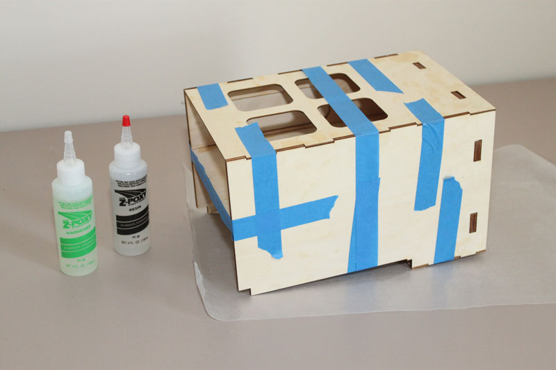
I’ll be assembling the Cherokee with Zap brand thin and medium CA and Z-Poxy epoxy and finishing resin from Frank Tiano Enterprises. Always have a well ventilated work area when using modeling adhesives.
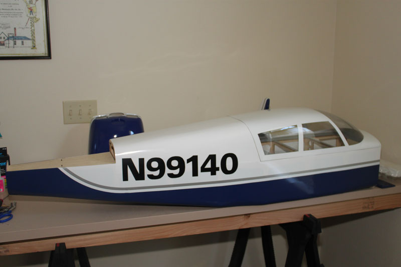
The airframe is covered in heat shrink film in a 3 color scheme that appears to mimic a Piper factory paint job. The model is built from laser cut balsa and light plywood and the components appear sturdy without being heavy. The fiberglass cowl, strut covers, and tail cone are painted to match the applied covering job. Carbon fiber wing and stabilizer tubes are included as well as 3 wheels and a comprehensive hardware package.
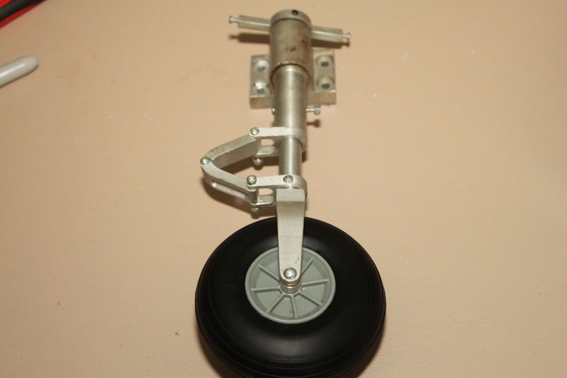
The RC Guys Cherokee also duplicates the full flying stabilizer or stabilator of the full scale model. The two piece stab is permanently joined during construction and is fully sheeted and airfoil shaped. Another nice touch is the very nicely machined oleo nose wheel strut that comes assembled and ready to mount to the firewall.
The covering job needed about an hour of work to seal some loose edges, and shrink down some air bubbles over the sheeted balsa surfaces. The tail of my plane was covered such that the over laps were backwards and the forward edges of the covering were exposed to the air stream so seal them very carefully. I had some covering on the vertical fin come loose during the first flight and it made an alarming sound.
The first decision that needs to be made is the power plant. The recommended engine is the DLE-55 and having downloaded the instruction manual before receiving the kit, I went ahead and picked up a DLE. After flying it with a 55 I believe anything from a good 35 on up would provide adequate power. There are also glow 2 and 4 stroke engines listed on the product web site but you’re a little more on your own here as the instructions assume a gas engine installation. If you prefer to stay away from wet power I think the Cherokee would be a good candidate to convert to a 10 or 12S electric without too much trouble.
Having the power plant on hand, or at least a firm decision made before you start is imperative. If you’re going with the DLE or any engine that swings a 22 inch prop you really need to move the mounts for the nose wheel strut and this is a LOT easier to accomplish before you assemble the engine box. The Cherokee kit includes a functional oleo strut so you need to take its motion in to account when figuring out your propeller clearance.
ENGINE BOX:
If you’re going to use the DLE-55, remove the blind nuts and use the nose strut as a template to locate the nose strut as far down as it will go. Some kits allow you to slide the motor box and mount it according to your engine needs. The way the Cherokee is designed, the engine mount is fixed and you have some leeway to move the cowl fore and aft to align the spinner. It took some sanding on all of the tongue and groove parts to make sure all of the parts fit together well. The motor box is a tight fit in the fuselage so take your time and dry fit all the parts or you will have a lot of sanding to do later. Also, when you glue the pieces together, make sure everything is tightly clamped or taped.
Some real thought went into cutting the tabs and slots for the engine box. There is already right thrust built into the firewall and all of the tabs will only line up if all the parts are correctly oriented. When the glue on the firewall is dry, sand the edges and any place that glue seeped out and install it in to the fuselage.
After I glued the engine box into the fuselage and epoxied the triangle stock to reinforce the firewall, I fuel proofed everything up front with Z-Poxy finishing resin. The finishing resin doesn’t need to be thinned and it takes about 6 hours to cure but it sands well and is easy to work with. Now you can set aside the fuselage and start working on the wings.
This step is one of the areas where it appears the manual includes photographs of a pre-production kit. The parts pictured aren’t quite what you’re actually working with but they do illustrate the steps quite well. As I said above, the tabs and slots won’t go together if you don’t have the parts in the right place and in the correct orientation.
WINGS:
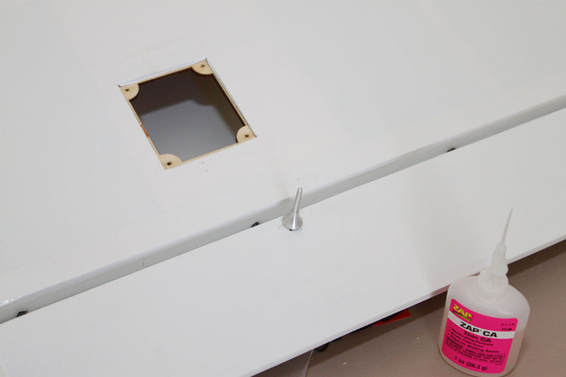
This is another area where the actual steps don’t match the supplied parts, though in this case it’s a pleasant surprise. The covering is already cut away for the servo hatches and the edges are sealed for you. The manual calls for Z bends on the servo end. I’m really not thrilled with this setup on a plane this size, and I mentioned this on a call to RC Guys but they assured me that they were fine for an aircraft of this type.
All of the hinges supplied are point style hinges and I find these hinges very easy to install and work with. You can glue them one side at a time and a little bit of Vaseline or light machine oil on the pivot will keep stray glue from gumming up the works. I dry fit the hinges and lubricated the pivots then glued them with 30 minute Z-Poxy. There was no drama here; all of the holes were drilled properly and consistently.
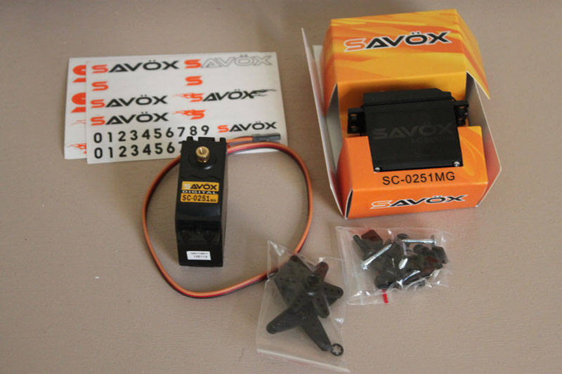
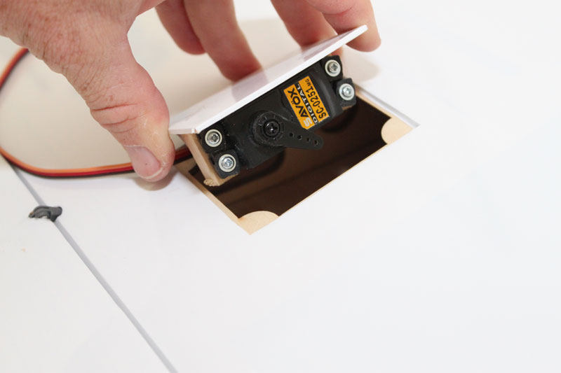
Several of the guys flying giant scale aerobatic planes at our field are speaking highly of Savox servos so I contacted HRP Distributers here in Jacksonville about my project and they supplied 8 SC-0251 metal geared digital servos for the Cherokee. These servos produce 180oz of torque at 6v, which should be plenty for the expected flight loads of the Cherokee and surpass their recommended minimum torque requirement of 70oz on most of the surfaces.
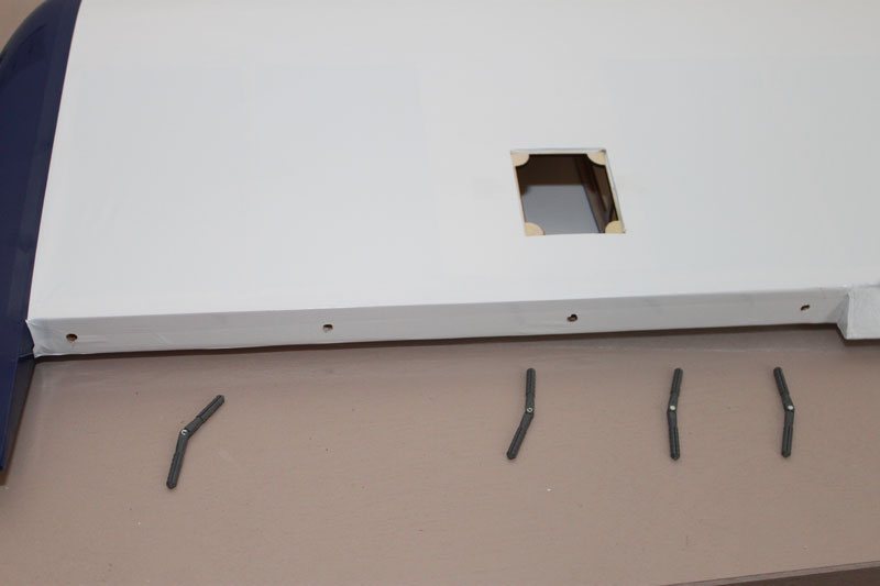
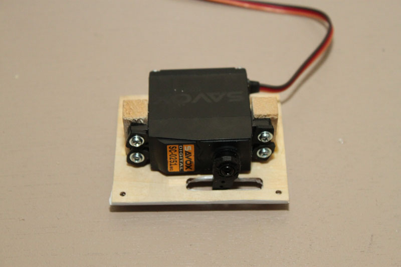
The servo mounting posts are already glued to the servo hatches. Some of them fit perfectly, others needed the posts sanded for the servos to fit between the mounting rails. The manual also recommends a bead of glue around the rails which I did to all of the servo hatches when I mixed 30 minute epoxy for the firewall.
One detail that was omitted from the manual, but Dan from RG Guys provided an immediate answer including a picture via email, was the flap servo orientation. The output shaft of the flap servo goes towards the rear. I did find out after the fact that there was plenty of control rod left over that needed to be cut off after the rod was installed so I’m not sure it matters either way. The flaps take a little tinkering to get the linkages setup correctly, take your time here so that the servos are perfectly aligned with each other so you get symmetrical flap travel. A programmable radio that has enough channels to allow individual sub trim of the flap and aileron servos will make this part of the installation go faster.
I tried Dubro heavy duty servo arms for the ailerons but they were too tall and that would have required some re-engineering, but a set of 1.5” SWB or Hangar 9 servo arms (Savox uses a Futaba spline) would be perfect for the aileron installation.
Installing the supplied control horns in the ailerons and flaps went exactly as documented in the manual. I used Zap thin CA to harden all of the screw mounting holes for the hatches and the areas where the control horns pass through the surfaces. Also, anywhere you’re screwing metal in to metal always use thread locker. The kit included some incorrect parts for this step, it seemed like I no sooner hit SEND on the email describing the problem than the parts were in my mailbox.
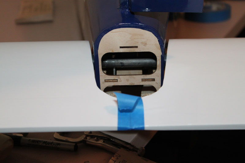
When you’re done with the wings it’s time to remove the covering and seal the edges where the wing tube, anti-rotation pins, and servo wires, pass through the fuselage.
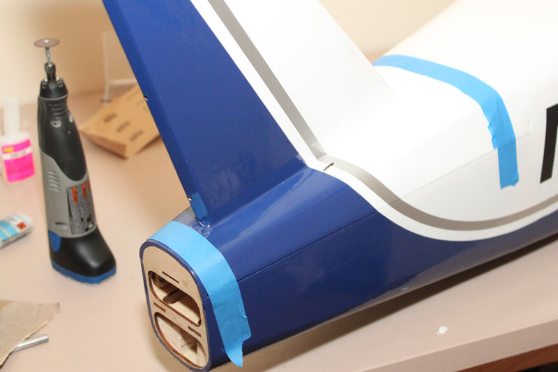
RUDDER AND VERTICAL STAB
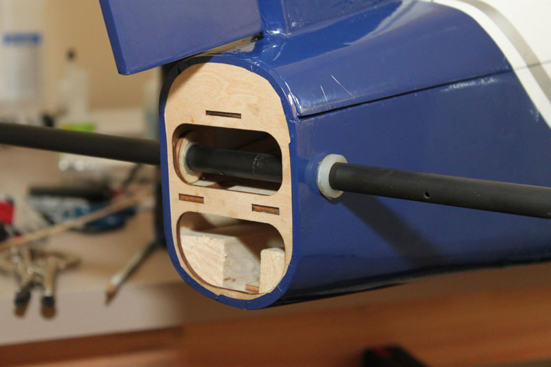
The manual provides very detailed measurements for locating and removing the covering from the exit holes for the rudder pull/pull cables. I just turned the shop lights out and used a LED flashlight facing backwards, and poked a hole in the covering where the holes lit up. The stab then gets glued in to the top of the fuselage with epoxy and the rudder hinges get installed just like the wings hinges.
STABILIATOR
The instructions state that there is a dowel “hiding inside the stab tube” that needs to be properly located and glued in place. After some frustration I came to realize, that like the servo cutouts, the dowel was already glued in place exactly where it needed to be at the factory. The 5 7/8 measurement for the hole wasn’t anywhere close to where it needed to be either.
Install the stab tube nylon bushings in the fuselage, center the tube with a ruler, push a servo and arm into the servo slot and mark the offset that you will need for the elevator rod, then, and only then, mark and drill the hole. A drill press helps make sure the hole is centered through the tube. I put a few drops of machine oil where the tube passes through the fuselage bushings and wicked some thin CA into the screw hole.
Unless it’s really unsafe we always build review planes as the instructions direct but I really felt that this was one area where a Z-Bend would be trouble. Flight testing proved this to be true, especially when over powering the plane.
I would use 2-56 threaded rod, attach the supplied clevis to the stabilator end and use a ball link such as the Dubro swivel link on the servo end. Play in this area, with the flight loads of a full flying stab, is a recipe for big problems in my opinion. The counter argument is that this isn’t doing 3D like a Yak, or 100+ mph like a war bird, but I prefer to err on the side of safety with a plane of this size and price.
When you’re done with the servo setup you can tidy up everything by installing the removable servo access hatch and tail cone. A little blue permanent marker and the screws become invisible from a few feet away.
RUDDER SERVO INSTALLATION
Nothing special involved with rigging the rudder servo or the pull pull cables; the installation went smoothly exactly as documented.
MAIN LANDING GEAR INSTALLATION
The actual landing gear installation proceeded as documented. I did run into a bit of an issue when I installed the strut fairings. The photo shows plenty of clearance between the strut and the flap servo hatch when locating the plywood mount for the fairing. I think this was another difference between prototype and production kit as my fairing block covered a portion of the flap servo hatch. I had to elongate the hole considerably to get the wood mount to fit without blocking the access hatch. That meant also elongating the hole in the lower wood fairing mount. Once all this was done, everything went together as advertised.
Some fiberglass wheel pants would really set this plane off.
Grind a flat spot on the leading gear struts where the wheel collar screws seat on the landing gear strut.
NOSE GEAR INSTALLATION
The provided oleo strut is nicely machined and fully functional. I had to tighten up all the hardware on the nose strut just use care that you don’t over tighten anything or it will prevent the oleo strut from compressing. If you’re using the DLE-55 you will need to relocate the nose wheel mount as described before. If you didn’t do this already, you’re probably going to have a fit retro-fitting it now.
It’s also time to decide where your throttle servo is going to be mounted which will be driven by your engine choice. Since the DLE has the throttle lever on the left, the nose gear servo will go on the right. The mounts for both the nose wheel steering and the throttle were both nicely covered in white covering on the outside surfaces. This of course will have to be removed to glue them in place, and depending on where you end up mounting the servos you may have to make shims between the motor box and the servo mount so the servo mounts are glued over their entire surface.
There is a pushrod provided for the nose gear but no clear description on how exactly to accomplish the connection. The manual pretty much drops off here on the nose gear installation and moves on to the throttle servo installation.
I removed the screws provided at the nose gear tiller and installed one of the black plastic control horns that I had left over from the improperly provided aileron hardware, and a longer screw. I had to drill a large hole in the firewall for the pushrod and clevis installation to clear.
Setting up the nose wheel steering without a computer radio will take a bit of tinkering. I had no real control over the tiller arm length on the nose wheel and even with a short servo arm I had to reduce the nose wheel steering servo throw to 50 percent of that of the rudder to make ground steering manageable and prevent the nose gear from binding.
The throttle servo installation is accomplished in a similar matter. I used a Z-bend on the throttle servo end and a nylon clevis on the carburetor end.
FUEL TANK INSTALLATION
The fuel tank provided works perfectly. I used a two line system with a T in the carburetor line to fill the tank. I mounted a Jem-Dot fuel dot mounted to the outside of the fuselage. Unlike some of the ARF’s manufactured today, there are no provisions on the structure for mounting switches or a fuel dot so I had to make reinforcements out of lite-ply for the receiver and ignition switches and for the fuel dot. If you want to follow a more scale appearance you could always do these internally but then you’d have to remove the canopy each time. This isn’t all that hard considering its only two screws.
I used Dubro tygon gas fuel line for the carburetor and vent lines and discarded the provided clunk line and substituted Viton fuel line obtained from Red Aero RC for the clunk.
I installed a few strips of self adhesive insulating foam on shelf in the motor box and two large tie straps to mount the tank and ran the vent line around the tank and out the bottom of the airplane.
ENGINE INSTALLATION
The DLE engine manual includes a mounting template that I downloaded and printed out. I lined up the laser etched lines and drilled the holes at the indicated positions. The stand offs that come with the DLE work well but you do have to relieve a large area of the firewall so that the rear mounted carburetor has clearance. Trial fit everything at this point including the spinner and cowl positions. Don’t install the muffler yet.
You could probably install a choke servo, the weight penalty would be negligible but I went the simple route and made a choke lever from an old push rod that can be actuated by hand through the cowl cheek. A few flips with the choke on and the engine will pop, a few more flips and the DLE is running.
When I was confident that the engine compartment installation was done including the nose wheel servo, throttle servo, choke lever, and nose gear strut, I removed each engine mounting bolt in turn and reinstalled them all with red thread locker.
Run the fuel lines at this time.
COWL INSTALLATION
Once the engine is mounted and the throttle connection is made, glue the hard wood blocks that will be used for the cowl screws to the firewall. I used 30 minute Z-Poxy and scuffed all of the gluing surfaces with 80 grit sandpaper.
You can use either card stock or masking tape to mark the center of the blocks, peel it back, install the cowl (don’t forget the spinner back plate so you can line it up properly) and drill holes through the cowl and into the blocks. In addition to the provided wood screws, I used bonded washers from RTL Fasteners to secure the cowl in place. These are the best I’ve found for vibration resistance and preventing the holes in the fiberglass from wallowing out. After the holes are drilled harden the threads in the blocks with thin CA.
After the cowl holes have been drilled it’s time to start cutting out the cowling for the muffler and air exit. The picture is close but they took off too much. Again I used masking tape to mark the position of the muffler and the center of the engine, and then I removed the muffler, transferred the measurements to the cowl, and installed a sanding disk on my Dremel. Install the muffler and start sanding. Take a little at a time until the cowl fits, nothing touches the cylinder head or muffler, and you have plenty of area for the cooling air to exit.
FINAL ASSEMBLY
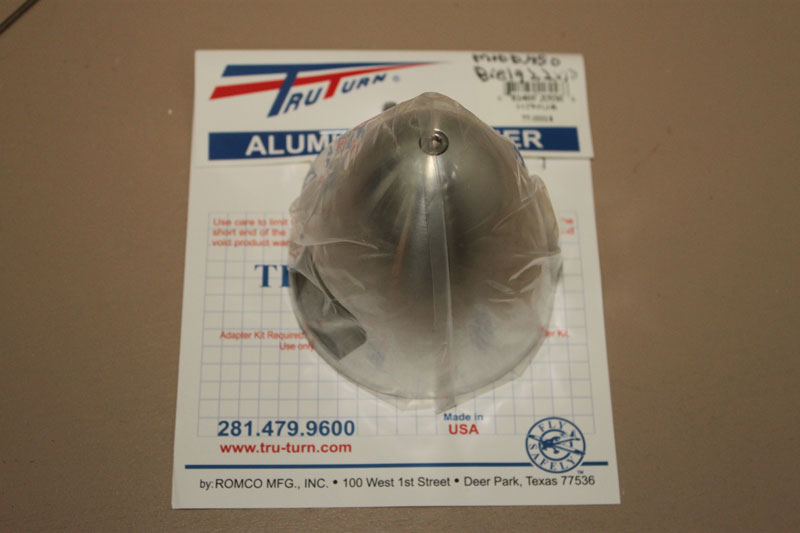
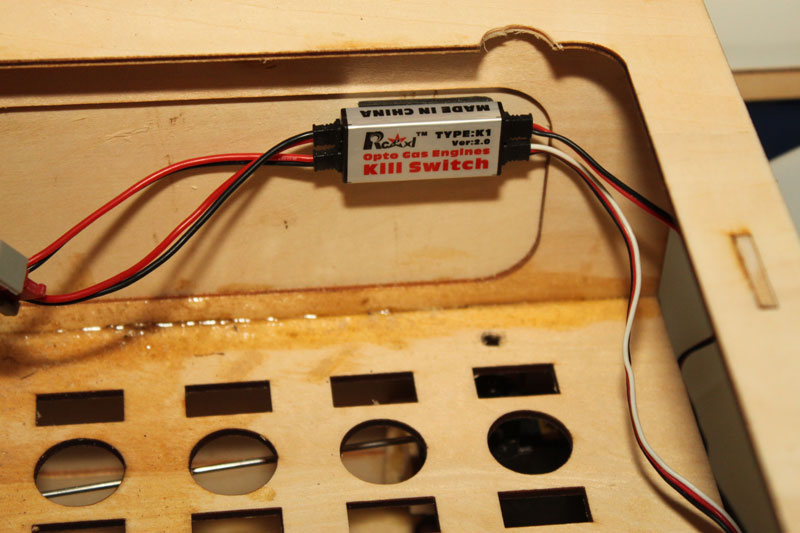
A Biela 22×10 carbon propeller was installed on the DLE-55 and a Tru-Turn aluminum spinner finished off the front end. The Tru-Turn spinners look great and are very well made. Two JR Heavy Duty Charge switches were installed, one for the receiver and one for the electronic ignition. I installed an RCExcel optical kill switch from RC Extreme Power so I had a second way to kill the engine from my JR 11X transmitter.
The AR9010 DSMX receiver was installed on the plywood plate near the batteries and rudder servo using the aforementioned foam insulation and secured with zip ties. I oriented the remote receiver 90 degrees to the main receiver with foam double sided tape.
I set up the control throws as outlined in the manual then set about looking for the CG. After searching the manual twice I found that there was no CG indicated. On a straight wing, the main spar is always a safe starting point so I played with the batteries until I had the CG centered on the wing spar. Conveniently enough, this ended up with the 5 cell receiver pack and the 4 cell ignition battery on the tray next to the rudder servo and the 9 channel receiver.
RADIO SETUP
A computer radio isn’t a must, the Cherokee could be flown on a 5 channel radio, but it sure makes life a lot easier. I used the channel mate function on my JR 11X and a 9 channel AR 9010 DSMX receiver so that each servo had its own channel.
Two Aileron channels were mated, set with the recommended throw, and 35 percent expo was dialed in.
Two Flap channels were mated, set on a 3 position switch, and given a .7 second delay in the servo speed menu for realistic looking operation. Full up, about 20 degrees in the middle, and as far down as the flaps would travel for the full down position which is around 40 degrees or so. Two Rudder channels were mated. The Savox rudder servo had a 3” Dubro heavy duty Futaba style servo arm installed and set to the recommended throw and setup with 35 percent expo. The second channel was used for the nose wheel steering and the throw was reduced until no binding occurred, this was further reduced during taxi tests until ground steering was positive without being overly sensitive. One Aileron servo was configured with the recommended throw and given 40 percent expo as I felt the stabilator might be sensitive in pitch.
One Throttle servo was configured. A throttle curve was added to reduce response around low stick to make up for the non-linear throttle response of gas engines.
The RCExcel kill switch used the remaining channel on a two position switch.
Fail safe was set to center the aileron, rudder, and elevator, deploy full flaps, and kill the engine.
SUMMARY
The Cherokee went together reasonably well and looks great when assembled at the flying field. The main issues I had were some incorrect hardware included in the kit and some issues with the manual including the lack of clear direction for the flap servo installation and lack of CG.
The hardware was replaced and photos of the flap servo installation were provided promptly with one phone call to RC Guys. I actually had a bit of a laugh when I talked to Dan from RC Guys as I realized I had dealt with him several years ago when I worked for the local hockey team and we had one of their R/C blimps.
The elevator linkage should be a ball link; the Z Bend on our kit simply didn’t cut it for flight testing.
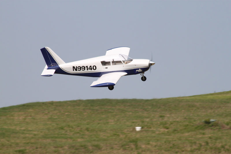
All that said, these are relatively minor issues and when you’re done you’re rewarded with a very good looking stand-off scale plane that flies extremely well. This would be a good plane to get used to flying large gas powered planes if you’re interested in getting into giant scale. Also if you’re into scale detailing, the Cherokee has plenty of room for details like a cockpit and other accessories.
 |
 |
 |
|
The Cherokee comes neatly packaged in the box. |
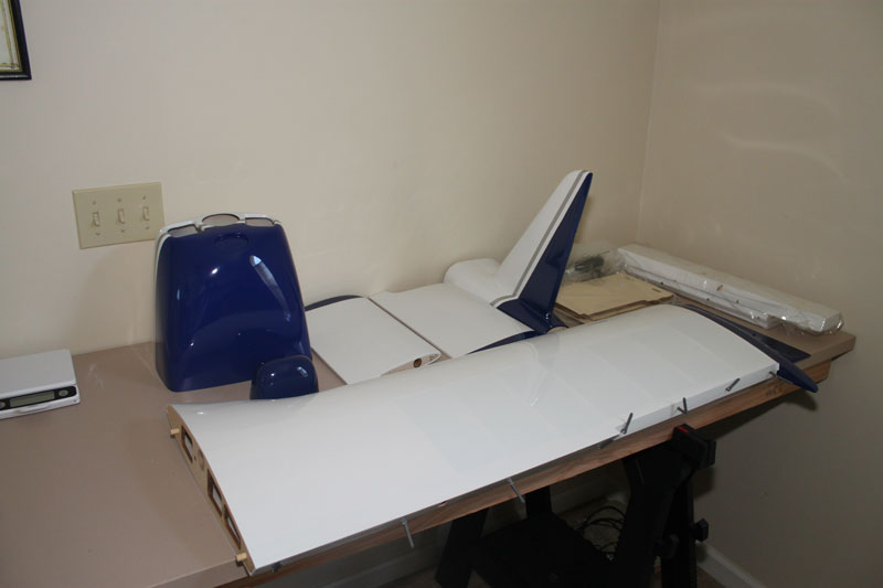
Components as I removed them from the box. |
The fuselage prior to starting assembly. |
 |
 |
 |
|
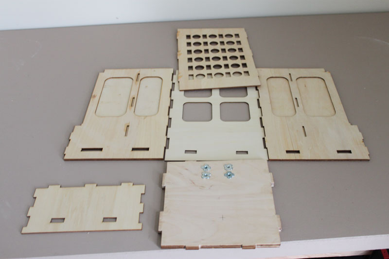
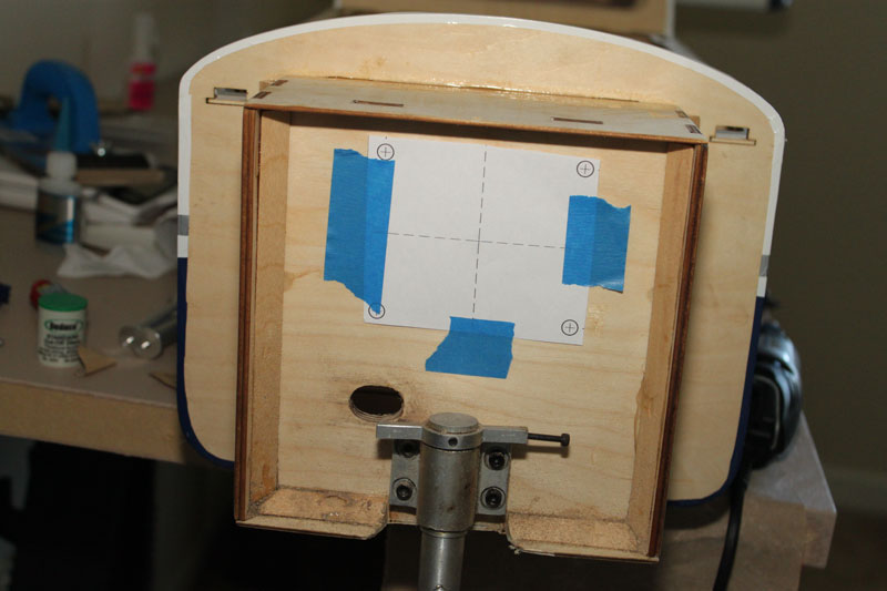
The firewall components prior to assembly. |
The firewall all glued up with Z-poxy. |
Pin hinges ready to install the control surfaces. |
 |
 |
 |
|
Savox SC-0251MG servos used throughout |
The servo installed on the access hatch for the ailerons. |
The control horn installed on the aileron. |
 |
 |
 |
|
The aileron servo being installed |
The tail is held in place, waiting for the glue to cure. |
The tail tube is installed. |
 |
 |
 |
|
The tail surfaces installed |
1785 |
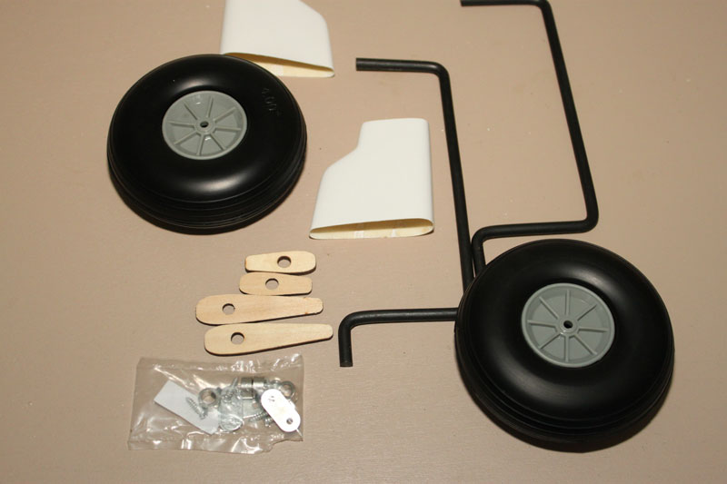
Landing gear components |
 |
 |
 |
|
The main landing gear installed |
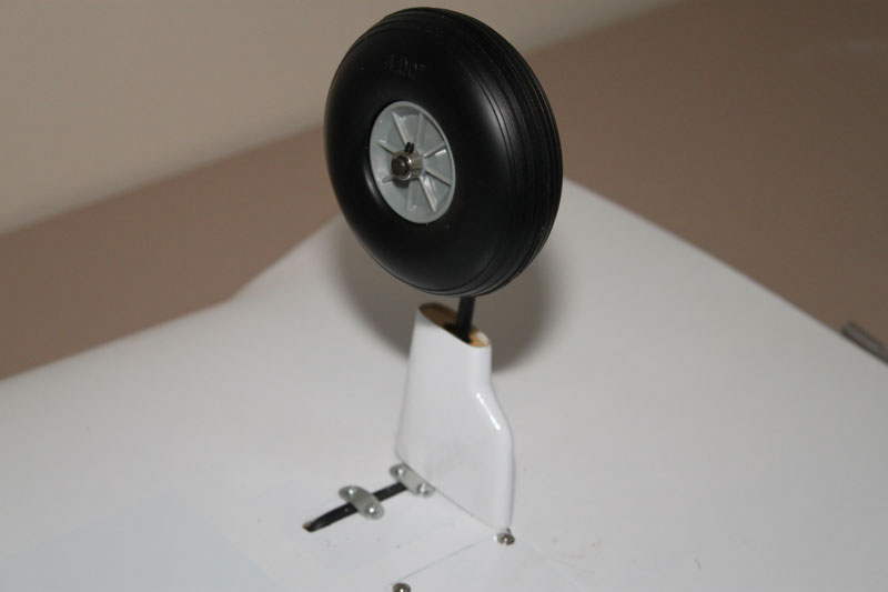
The front oleo gear. |
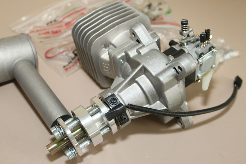
DLE Engine prior to installation |
 |
 |
 |
|
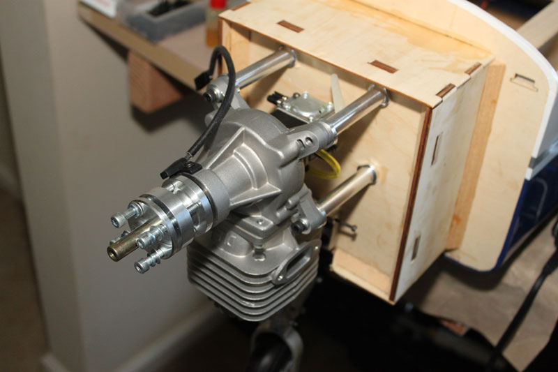
Engine mounting template on the firewall. |
Engine is installed with aluminum stand-offs. |
Tru-Turn spinner |
 |
 |
 |
|
Electronic ignition kill switch. |
