 Fly RC Magazine WE LIVE RC
Maxford USA Mentor-G V2
Giant-scale versatile trainer
Author: Cliff Becker cliffb@flyrc.com
Photographer: Walter Sidas
NEED TO KNOW
MANUFACTURER/DISTRIBUTOR: Maxford USA
TYPE: 26cc gas trainer ARF
FOR: Intermediate pilots
PRICE: $239.99
NEEDED TO COMPLETE: Radio system, five servos, engine and flight battery
SHORT DESCRIPTION
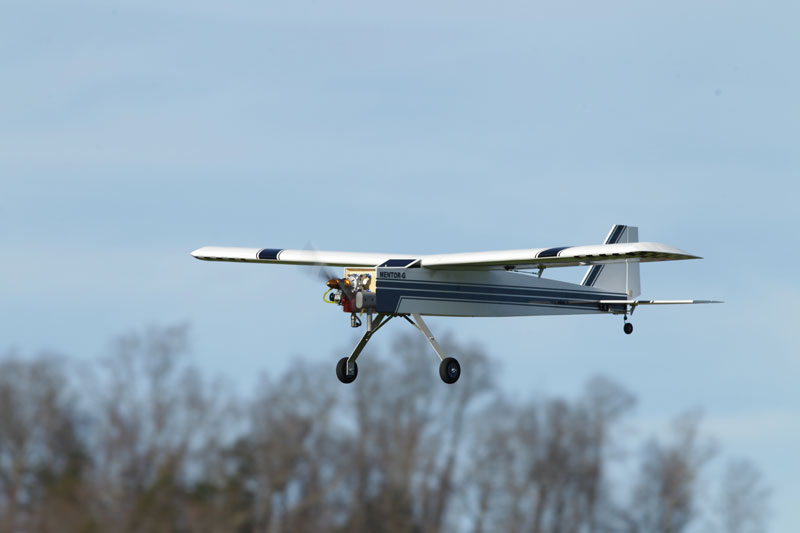
Maxford products are high-quality. The Mentor-G V2 is no exception. The fuse is all ply with the wings and tail surfaces are balsa construction. The landing gear has a very robust design for those novice landings. The covering can be repaired easily when damaged. This is a gentle giant in the air.
ASSEMBLY TIPS
After checking to make sure all contents were accounted for and touching up the covering with my heat gun, I started to assemble. Being an ARF the assembly process is quite simple. Although a simple assembly, Maxford has taken effort to assemble a well thought out manual with photos of the actual model in the assembly process. The model begins with the items you will need to purchase to complete the plane. There is also a parts list of the contents included in the kit. To ensure choosing the correct nuts and bolts, photos depict the hardware and its location. Blind nuts come already installed except for the engine because of the variety of powerplants that can be used and the servo trays have been predrilled to accept all the screws. The manual shows the throttle push rod going through fuel line. This reduces metal noise and I go one step further and use a plastic connector at the throttle point on the engine. Metal noise can interfere with the receiver resulting in losing control of the plane. Make sure that the horizontal and the vertical stabs are well-secured, square and flat to the fuselage. If not, you’re plane will be a bear to handle in the air. There was a small problem with the manual. Some of the hardware had been changed at the factory and not updated in the manual. For a novice this could be an area where some advice would be sought after to get the correct location for the new control horns being used on the ailerons, rudder and elevator. Maxford USA informed us that they are working on an addendum to correct this issue.
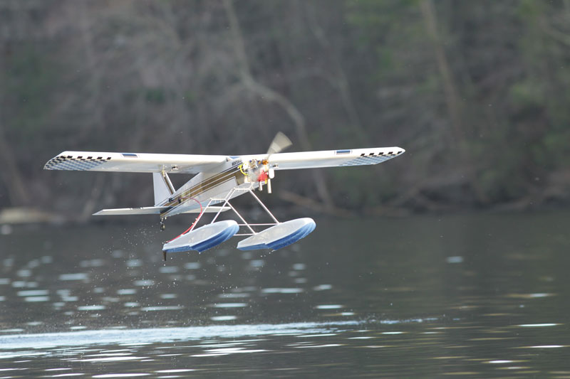
FLOAT ASSEMBLY
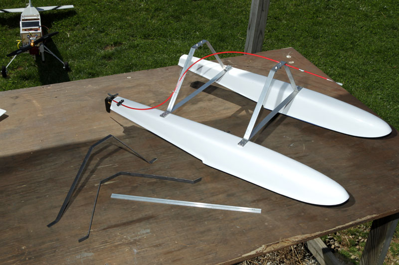
The floats, right out of the box, are a work of art… very clean and well-designed. There is a concave curve from the tip to the step along each side of the float’s bottom surface. This little extra effort in design creates turbulence under the float which helps break the float free from the water, especially useful on those calm mornings. Many float systems are just flat on the bottom resulting in more power and a longer run on the water before breaking loose into the air. Here are a couple spots in the assembly that could use some extra attention:
1. There was no mention in the manual as to where to place the step of the float in relationship to the CG. I’ve worked with floats before and knew the step of the float had to be somewhere around the CG. By looking back at some of my other float plane setups and also asking the opinion of a fellow float flyer, we came up with the same consensus. The best spot is one inch behind the CG. To get the correct position I marked the CG on each side of the fuselage and placed the floats on the base of the fuselage using a thirty-six inch straight edge and level along the straight edge down to the step of the float. This allowed me to get a correct measurement where the step was placed one inch behind the CG. It helps to have a second pair of hands to set this up. Once in place everything was marked for drilling and connecting the float brackets to the bottom of the fuselage. Using painter’s tape and a black marker alleviates trying to write on the covering.
2. The brackets that hold the sleeve and cable in place have two different halves. I didn’t realize it and on my first attempt I used two of the same sides. The sleeve would not clamp in place. I discovered my mistake and got the A and B sides together and the cable was then held firmly in place.
3. The cross spreader brace is three quarters wide, flat stock, pre-drilled aluminum. It’s very clean. The stock that is used to connect the floats to the plane is half the width, three times thicker and not pre-drilled. Due to its thickness and to make sure I got a perpendicular hole, I would have had to use my drill press. Instead I substituted aluminum stock, three quarters inch width and one eighth inch thick that I purchased at my local hardware store. I fabricated two new brackets. The stock I used creates a broader footprint with more points of attachment to the floats. Rather than two screws into the float, there are now four and the holes were easily marked by the cross brace’s pre-drilled holes. This spreads out the load and the aluminum gives a more esthetic look.
4. I also modified the rudder cable set up. The manual has the rudder cable running back to the plane rudder horn in the tail section, but the Mentor-G’s servos are in the tail section of the fuselage. So I saved some weight by cutting off ten inches of cable and attached the cable to the bottom of the rudder servo arm. I felt also that the wire cable was a little too flexible which did not give me good response to my inputs. I went with a Sullivan gold/yellow #508 cable set up and metal push rod set up instead. The curved part of the installation was where I used the plastic insert. With the straight parts, I connected the threaded push rods to the plastic portion of the Sullivan system. This gave me a very positive push and pull response to the water rudder. Being that I cut off ten inches off cable, I had to move the clamp that holds the cable from the tail section to in front of the servo. I placed a plywood block inside the fuselage on the ply side to add more thickness for the screws to dig into. All in all, using lighter material for the brackets and cutting off ten inches of metal cable, made the system came out lighter, stronger and with a more esthetically clean appearance.
5. When putting your floats together, lay everything out in its proper position. Before you drill and cut, make sure everything is properly placed: left is left, right is right, measure twice, drill once and cut once. I have spoken to Maxford’s technician and he plans to look into improving the float manual.
 |
 |
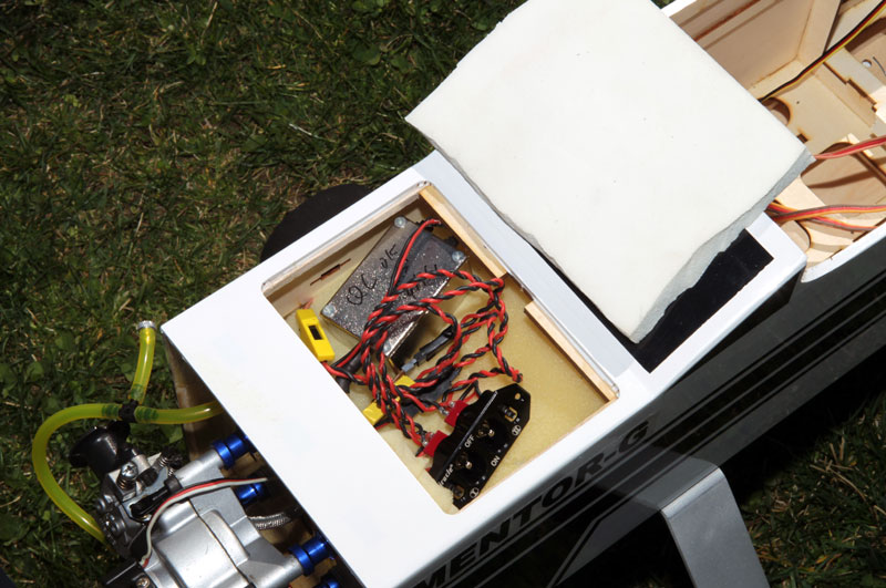 |
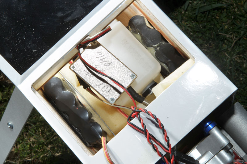
| Completed floats, ready to install. | Front hatch removed to show fuel tank and batteries | Second hatch removed shows the switch harness |
 |
 |
 |
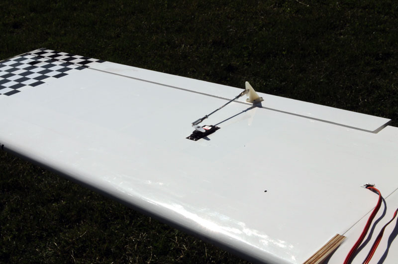
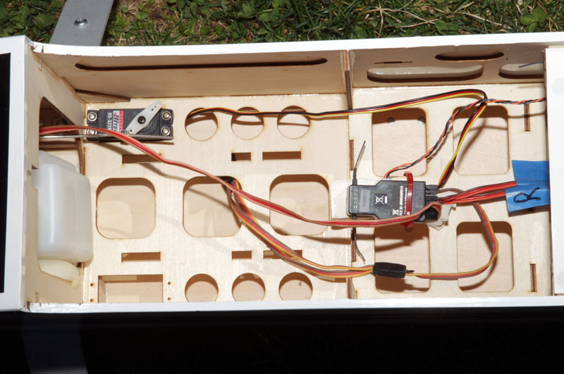
| Aileron Servo installation | There is a lot of room inside this fuselage. The throttle servo and receiver as all that occupy the space. | |
 |
 |
 |
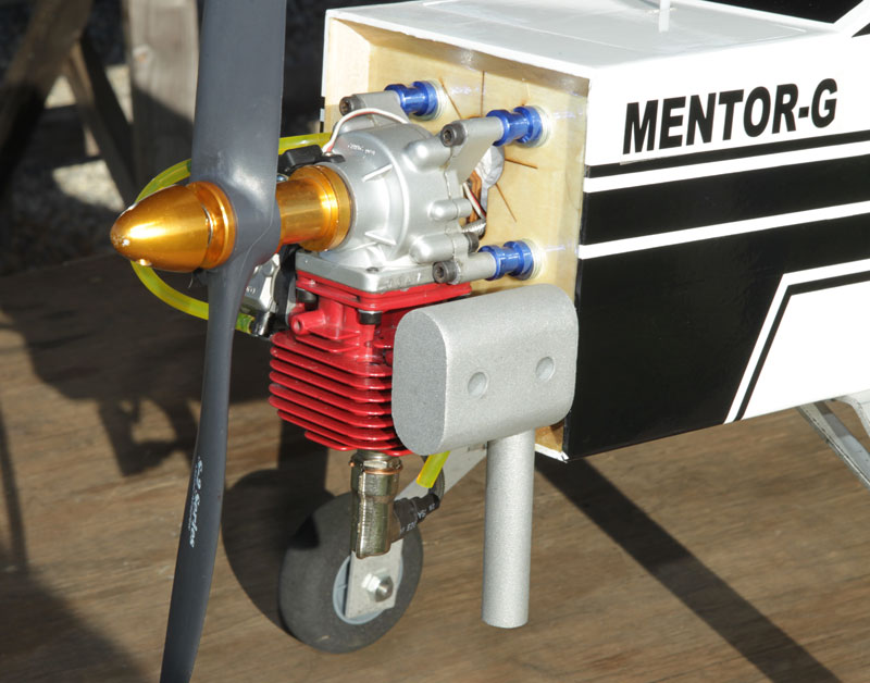
| The no-cowl design allows easy access to the engine |
Links:
CRRCPRO
HITEC
JR
MASTER AIRSCREW
MAXFORD USA
SPEKTRUM
SULLIVAN PRODUCTS
