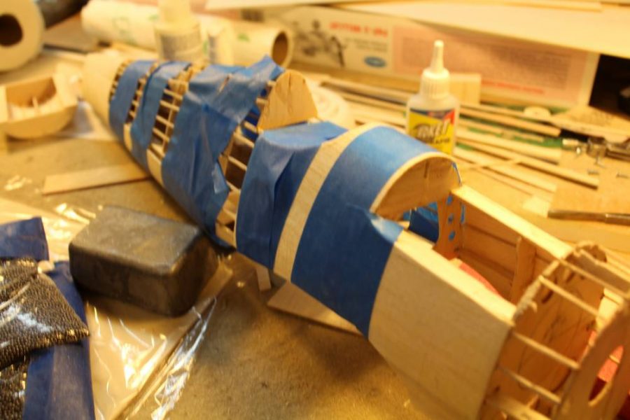
Let’s talk about that different technique of sheet balsa covering an open/stringered model airplane structure to create a better scale representation of a full scale sheet metal aircraft surface. I touched on the subject in my first Guillow’s Series article while describing the two Kit. No. 403 Spitfires you saw there, and I’ve given you plenty of hints earlier in this Hellcat feature, as well. What it comes down to is this. The best combination of improved structural strength, minimal weight gain, and “metal skinned airplane appearance” comes with attaching balsa sheet skin (the thinnest that you can manage is best) wetted with water , using a water-based adhesive such as Deluxe Materials Aliphatic Resin to do the bonding, and then wrapping/taping/weighting the entire structure while both the glue and the water dry. When this happens all the glue joints dry hard enough to hold tight while the wood is still wet. As the sheet balsa skin material dries it shrinks slightly. When that happens the entire assembly gains strength from the “pre-load” applied as the skin tightens and even more important, it becomes significantly more rigid/stiff and far less lightly to warp or otherwise distort than it might have been otherwise. None of this is my idea, by the way. I have found references to wet-balsa-sheeting on pre-WWII kit plans and magazine articles. Let’s get on with building this Guillow’s Hellcat and I’ll explain the details of the process as we go along.
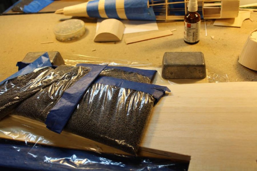
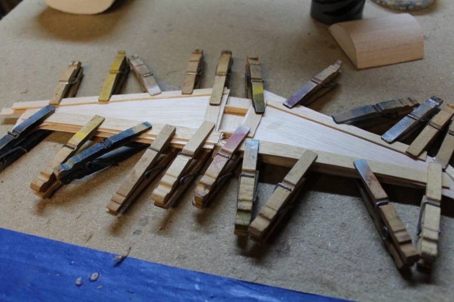
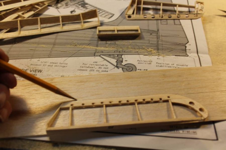
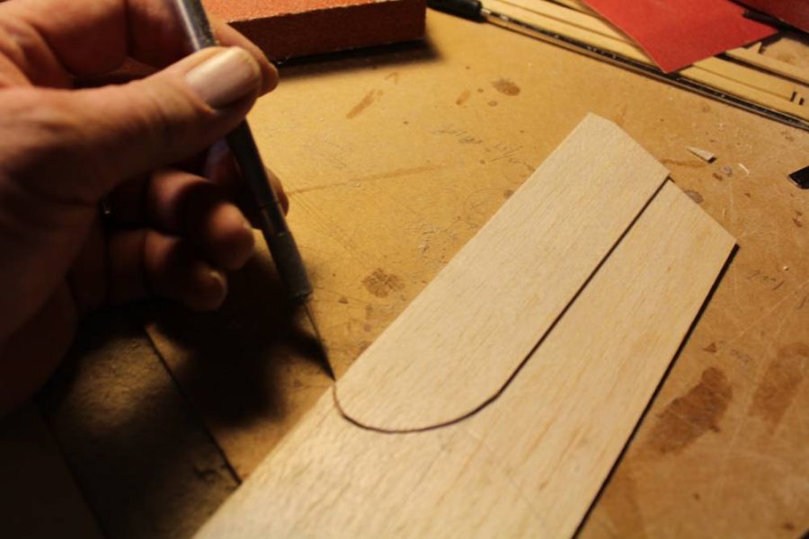
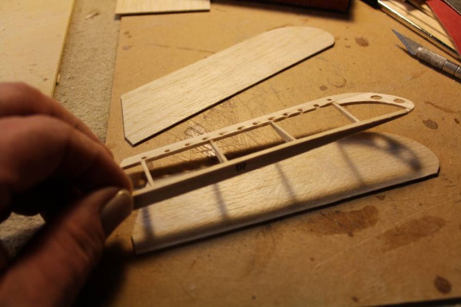
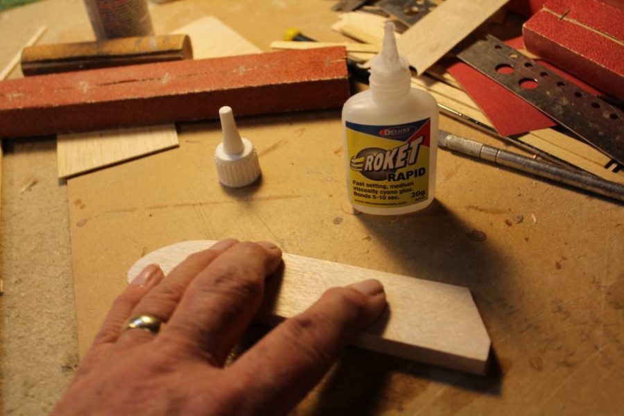
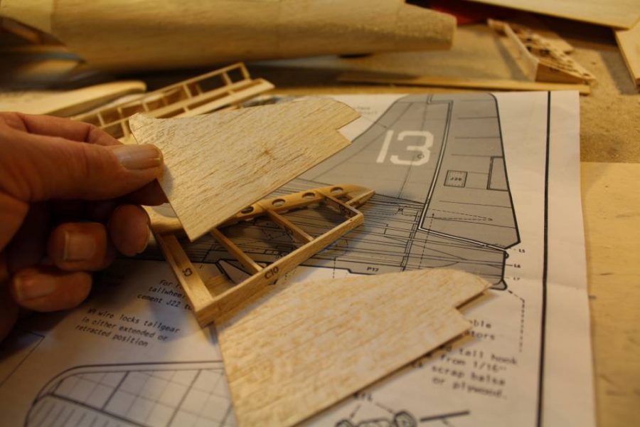
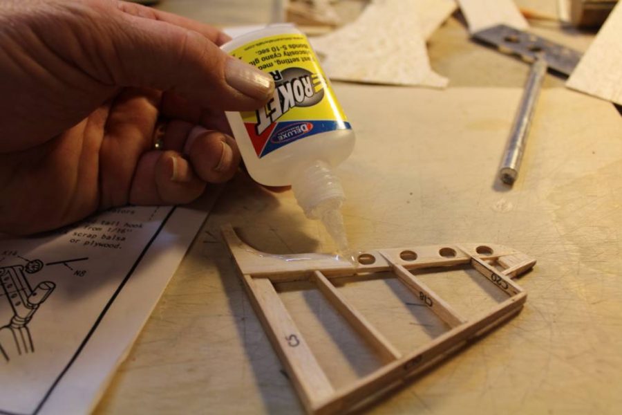
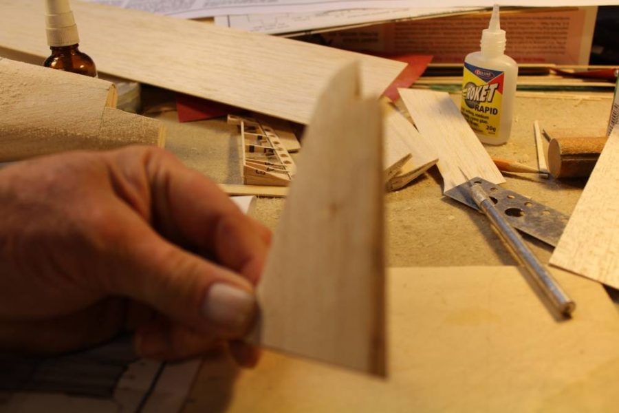
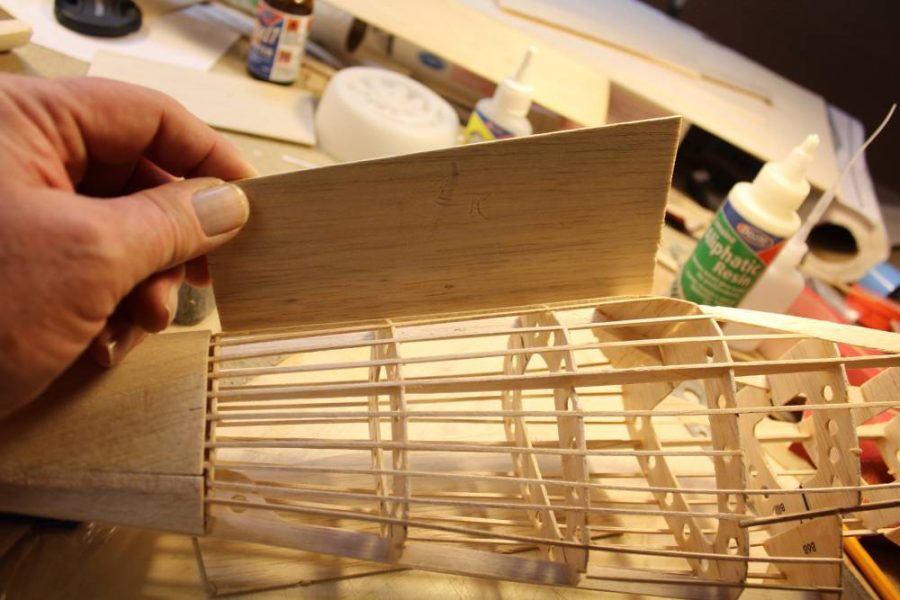
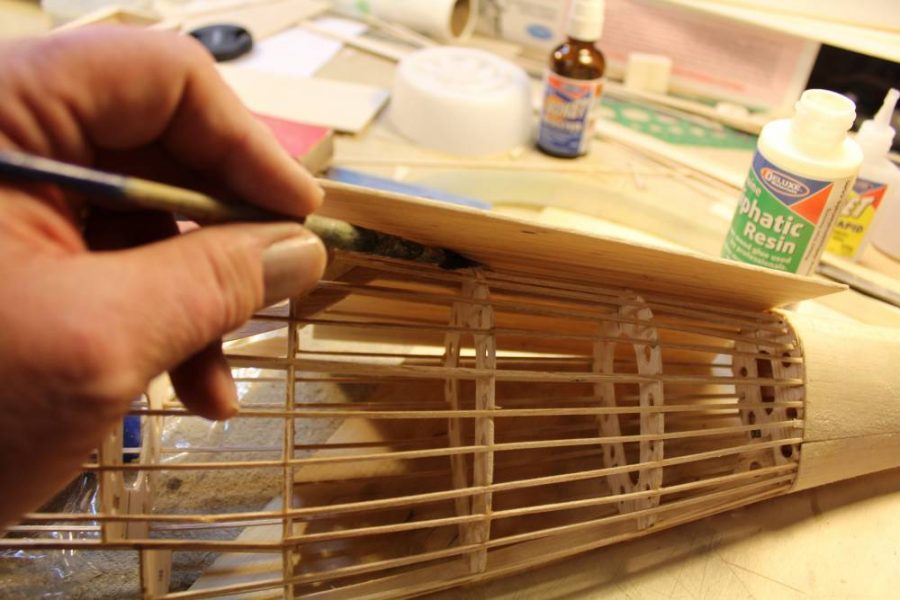
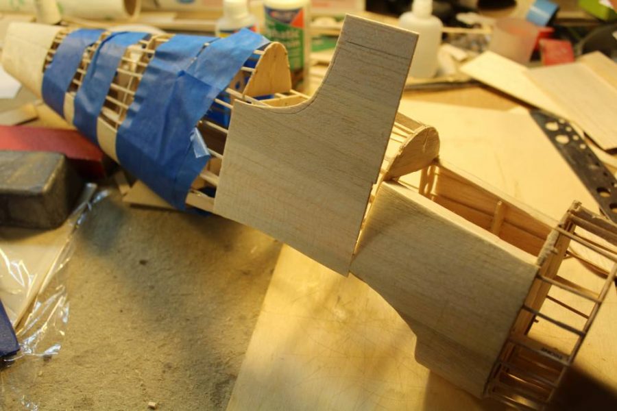
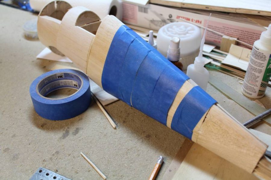
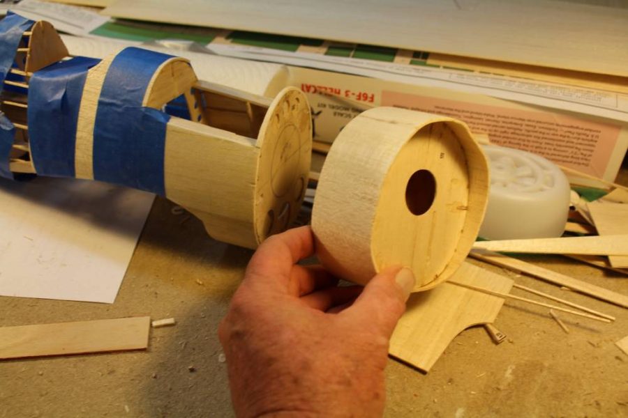
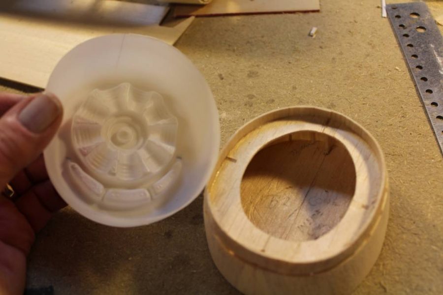
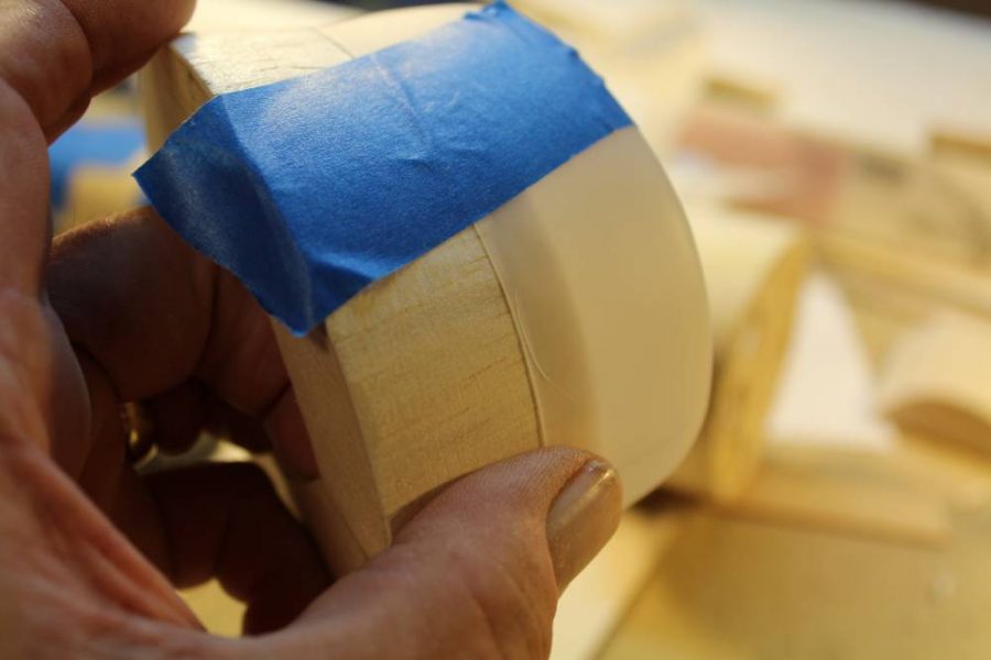
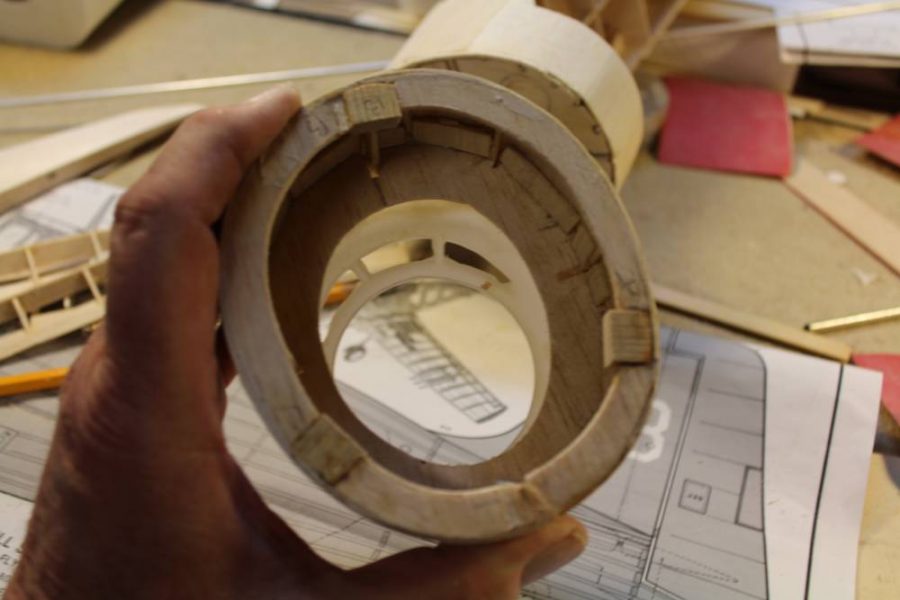
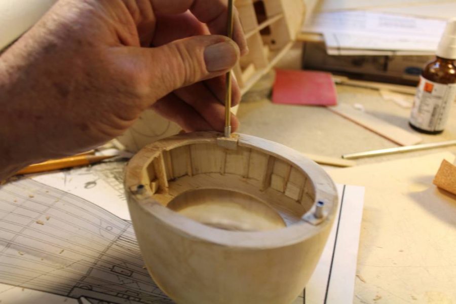
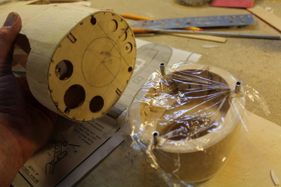
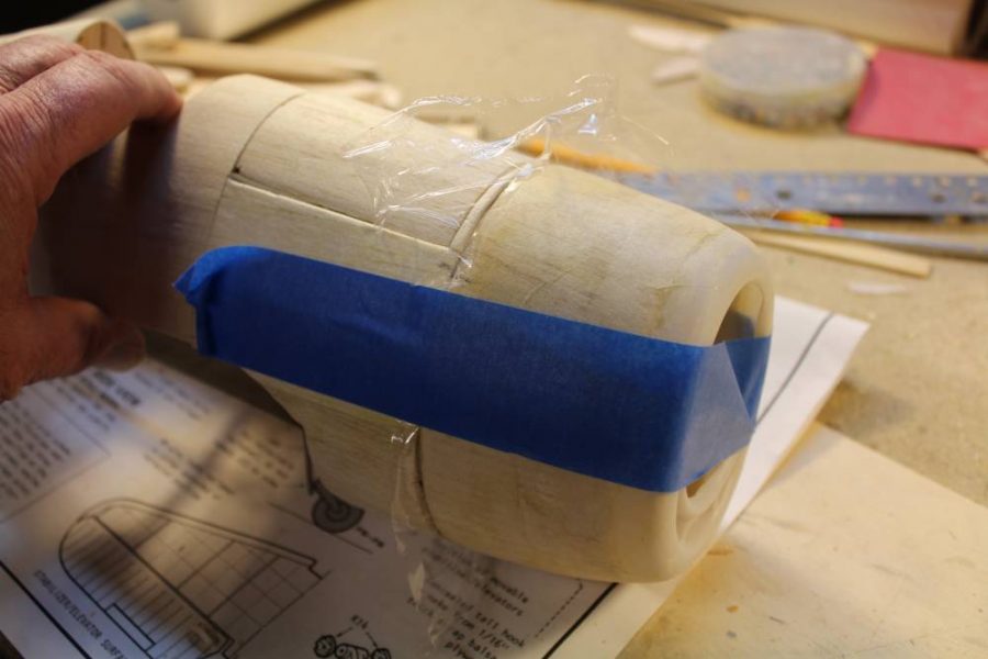
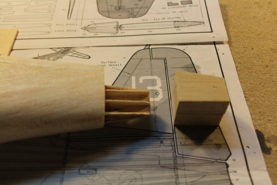
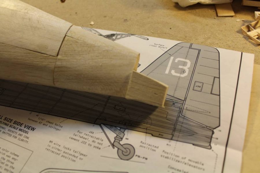
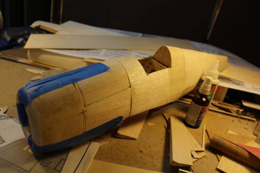
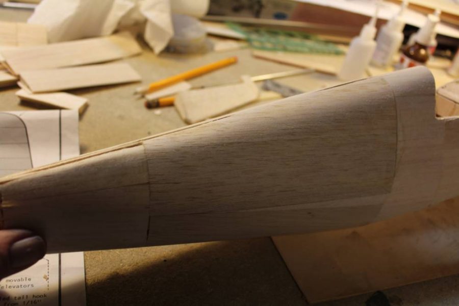
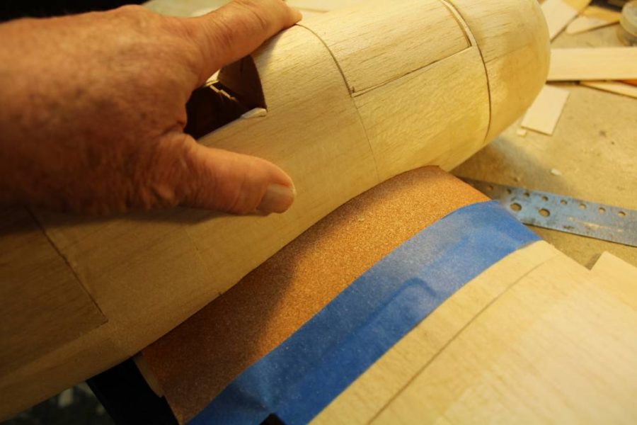
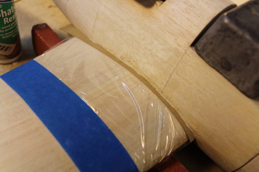
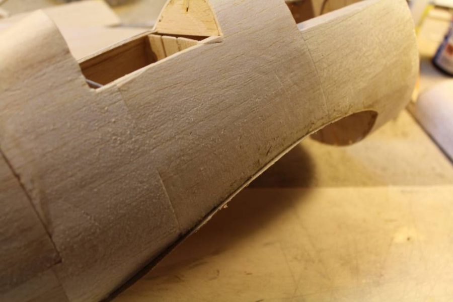
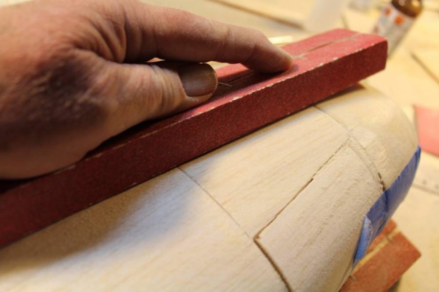
We finished the last shop session with what you could see of the right outer wing panel n early hidden under several plastic shot bags. Before we go any further I’ll describe these. A shot bag, which is nothing more than a really heavy bean bag, is a soft, comfortable building weight that we can use to hold unevenly contoured structures in place/together without creating any hard spots or stress points that could both damage and distort the structure. These shot bags are made from standard-issue heavy duty kitchen sandwich bags filled with several pounds of No. 9 lead shot and reinforced with all that blue tape. Fabric bags are probably more durable if you have the sewing skills to put them together, and you can use sand or some other fine, dense filler in place of birdshot if you prefer. In this photo you can see the right outer wing panel “bagged” in place for drying. Some of the little details count. See what looks like a sheet of 1/8” light ply beneath the left panel? That’s exactly what it is. I used those big lead building weights on the rear edge to hold it in place on my work surface, then shimmed ONE corner…the left trailing edge…up about ¼”, enough to force the top working surface of the plywood into a twisted plane that exactly defines the washout I want to build into the wing panel. The shot bags hold the wing panel with the top and bottom skins in place, still wet and freshly glued, while the whole deal dries overnight. NOTE: The wing center section (the bare balsa structure you see on the right), which is wide and totally flat on this Hellcat, was assembled as a wet wood/glue layup without any twist in the plywood base the day before I shot this photo. The center section, which is now strong, flat and stable is happy just sitting there waiting for the new stuff to dry.It turns out that there is more than one way to align and secure one of these wet sheet balsa covering assemblies. I used those shot bags on the top surface of each wing panel because the bottom, which is flat nearly all the way forward to the leading edge, with the result that it can be accurately aligned and supported on a flat surface such as the little sheet of plywood we just looked at. Set up that way it will hold the shape we want it to when weighted/compressed from above by the shotbags. NOTE: To make this arrangement work I pre-glued the leading edges of both the upper and lower wing skins in place first. Check back to our previous shop session (Hellcat No, 2) for a good look at this step in the assembly. Next comes a question. What part of the structure we have begun to build does not provide a flat base for alignment the way this wing panel does? That’s the case with the horizontal stabilizer you see here. It is symmetrically curved, top and bottom, and to surface it accurately we have to find a way to provide identical clamping pressure from both sides. Can you see how these clothespin clamps are just right for that job? Those scrap balsa strips distribute the clamping pressure evenly and prevent the clothespins from digging into the sheet balsa surface.We can get a better look at how this process comes together using one of the elevator sections, which tapers from front to back as well as from root to tip. Here I’m tracing the elevator outline on a piece of the soft/light 1/32” balsa sheet I’m using on the tail surfaces to help control weight.Once that piece fits, I trace and cut out a duplicate.Now you can see how the elevator “core” and both outer sheet skins line up for assembly.This time I’m using yet another method for aligning/clamping this elevator assembly together. Off camera, I water sprayed both sides of each 1/32” balsa sheet skin, then applied a line of Deluxe Materials Roket Rapid to every part of the core that will come into contact with the surface skins. When all this lines up correctly I apply controlled hand/finger pressure all around while making sure that every taper…top-to-bottom etc…remains even. Don’t try this with a wing…it’s too big and will get away from you. For this “by-hand” method to work, any assembly has to be small enough to control completely with your hands all at once.Here’s the same deal coming together on the vertical tail. I have both 1/32” balsa sheet skins cut to size.I’m applying an even bead of Roket Rapid on every joining surface.I’m not just hanging on… here’s what it looks like as I maintain just a bit more finger pressure through that lower leading edge curve while everything sets hard.Let’s get back to the fuselage while these tail surface layups have time to dry. Earlier I started working on sheeting the fuselage by closing up the rearmost section between formers B10 and B-11. I did this in equal left and right halves to avoid tight curves around the top and bottom that would threaten to crack the sheet. Here I’m going to use the same method , starting with the left fuselage side, but I’m taking advantage of the single-curvature of the fuselage outline all the way forward to former B-7 to use a single, larger piece of 1/16” balsa sheet for each side. It’s a good idea to do this whenever possible…the larger skin section eliminates several edge joints and reduces the opportunities for the sheeting job to the stringers out of line.Just as I did last time with the wing, I used a bead of Deluxe Materials Roket Rapid for an open-joint assembly of the precisely shaped skin section to the top keel, then water-sprayed the sheet. Now I’m brushing Deluxe Materials Aliphatic Resin onto every portion of the fuselage structure that will come into contact with the skin.Once that’s done I use plenty of that wide blue masking tape to pull the wet balsa sheet tight against all the places where we want it to stick…and hold it there. With this particular assembly I’ve chosen to skin each side of the fuselage separately, mostly because masking tape won’t stick to wet balsa and I’ll need the opposite side dry to serve as a place to stick it. Once that assembly was taped as securely as I could get it I moved ahead and used the Roket Rapid edge-glue technique to begin attaching some of the right fuselage side nose skin.With those new skin sections fully taped I have to let everything dry thoroughly/overnight before I can remove the tape and expose the remaining open bays for completion.With everything that I have assembled so far dry, I finished enclosing a few more of those open bays. The tape you see here is securing the corresponding 1/16” balsa sheet panel on the right side of the fuselage.Once again all that stuff has to dry, so I used that time to work on the nose…specifically the part that’s going to become the removable cowl. Do you remember that 1/16” plywood firewall/former that I added to the fuselage structure at B-2 instead of B-1? (NOTE: Like many Guillow’s kits, this Hellcat includes a revised firewall former made from a white vinyl material. Early kits used 1/16” plywood and I prefer this approach. In my experience those new vinyl parts weigh two to three times what the plywood equivalent would as well as being less dimensionally stable and otherwise more difficult to work with.) When I made the new plywood firewall I also made a 1/16” balsa duplicate. Here’s what I did with that. I cut off the entire front of the fuselage at the face of the plywood firewall, leaving B-1 with a bunch of stubby stringers attached to one side. I lined up the “open” ends of those stringers with the extra B-2 and glued up the entire assembly, then used some more of that soft/light 1/16” balsa sheet to wrap a new skin all the way around the outside of that new base cowl section like this. Note that I left plenty of extra 1/16” balsa sheet extending to both the front and rear of B-1 and B-2 so I’d be sure the new skin would easily fit that slightly tapered structure. What you see here is the original B-1 and the extra-balsa overlap that’s ready to be trimmed off flush with each former.Here I have enlarged the opening in B-1 to provide clearance I’ll need later. The extra B-2 at the bottom/rear has not been similarly trimmed. I’m holding the stock Hellcat kit plastic cowl with the basic dummy engine molded into it still in place. Can you see where I have “relieved” the outside face of the 1/16” balsa sheet skin by approximately the thickness of the plastic cowl for about ½” back behind B-1?Here’s why I did that. You can see through the translucent plastic cowl just how far it fits back past B-1 for a secure overlap joint with the outer skin. Off-camera I glued this entire joining area with Deluxe Material Roket Rapid (for open joints) and pressed the whole assembly into alignment. What you can’t see here is how the length of this new “scale” cowl matches the original distance on the plan from the front of the cowl to the original B-2, which coincides with the scale location of the rear edge of the cowl. NOTE: The whole point of this exercise is to provide a cowl with a nearly-scale outline and a cowl-to-fuselage parting line/joint that agrees with the scale location shown on the Guillow’s Action Plan. I’ll get into the details of mounting this scale cowl next…but… I want to be sure you understand that this extra work is not necessary. If you prefer you can build the nose from B-1 through B-3 exactly per the plan, attach the plywood firewall to B-1 as instructed , and fit the unmodified plastic cowl into place as designed. I went through the extra drill because I like the scale appearance it provides and to prove that it’s practical to add this touch of authenticity while adding very little weight.This is the modified cowl assembly seen from the rear. You can see that I have trimmed/opened up the new B-2 and added “hard points” of either spruce or basswood at three locations around the circumference. These will hold the cowl attachment/locating pins that are coming next.Those look like this. I have cut and fitted short pieces of 1/8” “standard hobby shop” aluminum tube to fit all the way into these hard point blocks for support and to extend about 3/8” back behind B-2.With all those locating pins glued into place I marked where they met the plywood firewall, then drilled out new holes at those points for 5/32” O.D. tube…the “next size up” that telescopes over the 1/8” pieces. Because it’s way difficult to “back-engineer” a modification like this to get a perfect pin-to-tube alignment, I’ve drilled the holes in the firewall slightly oversize. When I protect the cowl from unwanted glue adhesion with that clear wrap and then slip the tubes in place over them I get enough tolerance/wiggle-room for the assembled outer tubes to seat themselves easily into Deluxe Materials Roket Gel waiting in the holes.When I get everything into place it looks like this. The blue masking tape keeps everything in alignment while the Roket Gel cures and the plastic wrap prevents it from gluing the removable cowl into place.While that assembly sets I can work at the other end of the fuselage. In the original kit design the tail cone is made up of several die-cut contour filler pieces that extend the lines of the fuselage stringers into a faired aft edge. There’s no way this would not look weird with the rest of the fuselage sheeted, but to try to work with more 1/16” balsa sheeting around that small cross section would be frustratingly difficult at best. I chose to rough-out a block of light balsa to replace all that.With the “extra” stuff cut off it’s easy to glue the new balsa blank against B-11 in its place. We will finish shaping it later.A taste of things to come. Here I have added the nose cowl and battery hatch and secured them with masking tape to give you an idea of where this is taking us.By the time I got the fuselage structure in the previous photo all sanded out, shaped and smoothed there were a few places where my less-than-perfect work left me with some extra openings in the fuselage skin.Rather than trying to “patch” them with filler, I’ve added real patches of silkspan attached with Deluxe Materials Eze-Dope just as the “real” silkspan surface is going to be put on later. Doing this adds measureable strength with negligible weight gain and won’t show under the final finish.Earlier in the process of building the modified Hellcat fuselage I added 1/16” balsa sheet skin “around-and-over” the original “L” formers that define the wing saddle. According to the original kit design the completed wing would be permanently glued to these and the bottom/center “fillet” of the fuselage would be built into the open space left below the wing. Because our wing is going to be removable we are going to do things differently. For a start I’m going to “true-up” what’ going to define the shape of the new wing saddle structure by taping a sheet of 100-grit sandpaper to the top center wing surface to turn it into a custom sanding block that will define its own attachment base. Can you see how sliding the fuselage “gently-but-firmly” spanwise (side-to-side) across the abrasive surface will cut away excess material and “mate” the opening in the fuselage to the already-shaped wing? NOTE: I’m going to add a reinforcing plate of 1/64” plywood right here, so I will sand back/cut away enough extra wood…go deeper into the fuselage…to compensate for that plywood as well as the thickness of the balsa sheet skin I have already added to the top wing surface. Not doing this would force the wing to rest too low in the fuselage.I missed a shot! Off-camera I fitted a sheet of that 1/64” plywood to extend just outboard of the fuselage sides along the opening in the fuselage bottom from the leading to the trailing edge. What you see here is the joined-up assembly of the wing and fuselage with that plywood sandwiched in place between them. It’s glued to the fuselage with Deluxe Material Aliphatic Resin and protected from sticking to the wing by that clear plastic wrap.Once that has happened (overnight again) I used a pair of small snippers to rough-cut the protruding portion of the 1/64” plywood as close as I could to the fuselage sides and then……went back to the 120-grit sanding block to finish those edges flush with the balsa sheet fuselage skin. You are looking at the left side of the fuselage here, from the tail and down from the top. That’s the new battery hatch cover taped in place on the right.
Next time we will get on with making the actual working removable wing parts.
 Fly RC Magazine WE LIVE RC