 Fly RC Magazine WE LIVE RC
Author:
David Mielke davidm@flyrc.com
Photographer:
David Mielke
A down in the dirt discus launched glider
NEED TO KNOW
MANUFACTURER: Top Soaring
DISTRIBUTOR: Hobby Club
TYPE: ARF discus launch glider
FOR: Beginner to intermediate glider pilots
MINIMUM FLYING AREA: Small baseball field
PRICE: $135.00
INTRO
The Hobby Club Mini TopSky is a 1 meter (39 inches) discus launch glider. It features an immaculately constructed, completely bagged fiberglass wing with a blue foam core and top, bottom and leading edge carbon fiber spars, spiral wound tail boom and pre-molded equipment pod. It uses a small D/HLG glider specific Mark Drela designed AG03 airfoil throughout the length of the wing. It also comes with a complete hardware set including correctly sized servos for installation into the equipment pod. The tail sections and launch peg are also customizable to suit your needs and flying style. The model is suitable for all DLG situations in 0 to 10 MPH of wind and gives some great flying characteristics suitable for high and low lift situations.
ASSEMBLY
The first step in the Hobby Club Mini TopSky assembly is to prepare the wings for assembly. This is easily accomplished by putting the wing attachment screws in the pod, holding the wing root for each wing up to the mounting location and marking (with a foam safe marker) the location for the wing bolt holes. Then using your sharpest hobby knife cut out an area about two times the diameter of the head of the wing attachment screws (circular or square it doesn’t matter). This will be filled in with epoxy to give a solid seat for attaching the wing. I put tape on both sides of the wing and poured in epoxy while standing both wings with the wing root up. I used fast cure epoxy so that it didn’t have time to seep under the tape. After it was dry I removed the tape and trimmed the epoxy to the exact dimensions of the wing root.
Now I was ready to join the two wing roots. Since this is a rudder and elevator glider the wing is designed to have a fairly significant dihedral to allow for rudder turns. I put a piece of tape on the flat portion of the wings underneath the joint. Next I put one wing flat on my work surface and propped the other up at one point on the wing tip. I like to use this method rather than propping up both as I feel it is more accurate. Then I slightly lowered the wing and filled in the gap at the wing roots with 90 minute epoxy (used to give a wicking and solid cure), then I raised the wing back up and wiped off the excess epoxy that squished out.
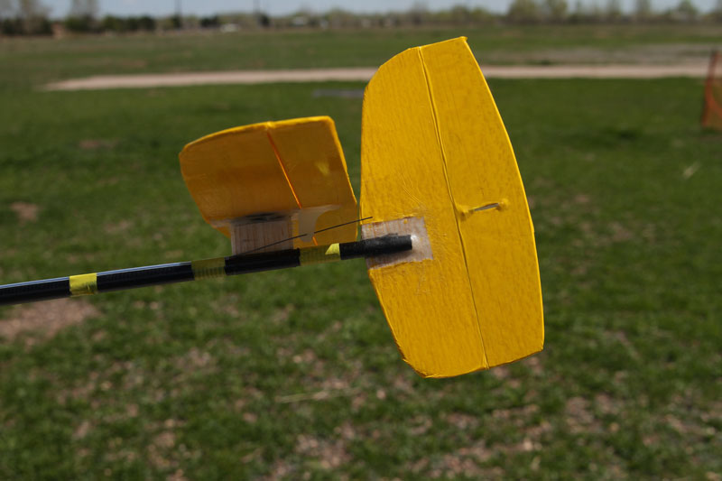
While I was waiting for the wing to dry I worked on the tail. The MT comes with laser cut balsa blanks for the horizontal stab, elevator, vertical stab and rudder. Following the manual I sanded the edges and hinge points to the required angles. Then I covered them using the included heat shrink plastic covering using a medium (not hot) iron. The folding technique described in the manual for hinges (which works great by the way) keeps you from having to do tape hinges. Now you have to remove some of the covering on the 2 stabilizers so you can epoxy them to the rest of the airframe. Don’t do this before you shrink the covering or it will pull back from where you want it to be.
I now built the small spacer that raises the horizontal stab/elevator combo up for clearance from the tail boom. This is a very important step so I followed the manual directions to the letter and was later rewarded with great flight characteristics, so if you are not absolutely positive your method is better use the factory method!
The next day my wings were dry from joining and it was time to put on the top and bottom layers of fiberglass and carbon to strengthen up the wing joint. The manual gives you some latitude on what method and location to use the different materials. I chose to put the carbon fiber on the bottom of the wing (which in my opinion has the most stress) and 2 layers of fiberglass on the top surface. My chosen method is to use a piece of foam and wax paper to cushion a sand bag to cover the layup and give a smooth finish. Again using 90 minute epoxy I laid up the top side layer blotted away all of the excess epoxy and let it dry overnight. The next day I did the same thing using the carbon fiber cloth and did the bottom. Remember to rough up the surface of the wing before you apply the epoxy for good adhesion.
When I had the wings completed I very carefully measured, marked and drilled the wing mounting holes through the epoxy inserts created in the first step. I deviated from the instructions in this area solely because I had gotten ahead of the instructions and forgot to grind out these locations when the instructions said I should. If you are careful either method can be successful.
Next I mounted the vertical stab/rudder to the boom by cutting a slot in the boom and the vertical stab. Definitely don’t mount the tail boom to the pod before you mount the stab because you want to use the mounted stab and wing to make sure everything is aligned when you mount the boom. After cutting the slots I joined them together and covered each side of the boom/tail joint with fiberglass and epoxy. After this dried I mounted the wings and epoxied the boom to the pod while measuring the distance from the vertical stab to the wing tips for correct alignment.
Finally I mounted the stab and elevator combination on the boom with a fiberglass wrap for strength. It is very important to make sure the stab and wing are aligned when you do this.
Now you have a compete airframe ready for RX, servo and control rod installation.
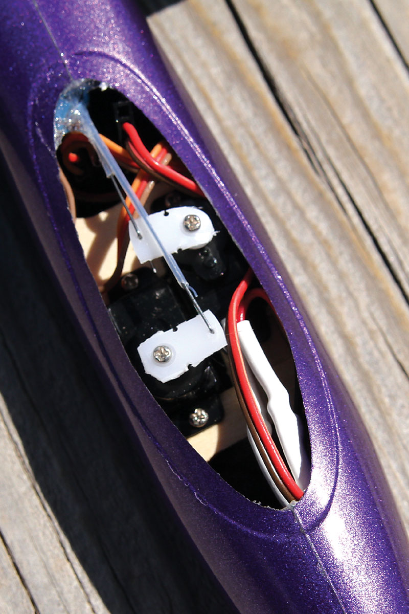
Installing the servos and radio in the pod requires the installation of a servo mount plate. I spent a fair amount of time making sure that everything would fit and operate correctly before I installed the plate. I found that I needed to shift one of the servos by about ½ an inch for proper clearance. I accomplished this by carving out some extra material and adding an extra piece of ply on the opposite end of the servo. Then I tacked the plate in place using CA, checked the clearance for the servo and RX insertion and epoxied in the plate using 5 minute epoxy.
The servos and RX installed I drilled holes in the back of the pod for the control rods. Carefully I inserted the control horns into the control surfaces using thick CA and installed the control rods and guides. I tacked the guides in place at the back of the pod and near the servos using shoe goo and custom cut some servo arms to give the maximum travel to fit in the pod. I started by using the circular “arms” and cut them down so I could drill a hole in a non-predrilled spot to get the correct size hole in the arm.
Construction complete I inserted the RX, servos and battery and checked the center of gravity. I found that it was slightly tail heavy so I added ½ oz. of weight to the nose. This gave me a CG exactly in the center of the recommended starting limits.
 |
 |
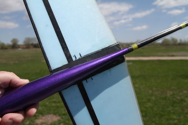 |
| Rudder and Elevator servo installation | Rear tail surface installation | The main wing as it joins the fuselage. |
 |
||
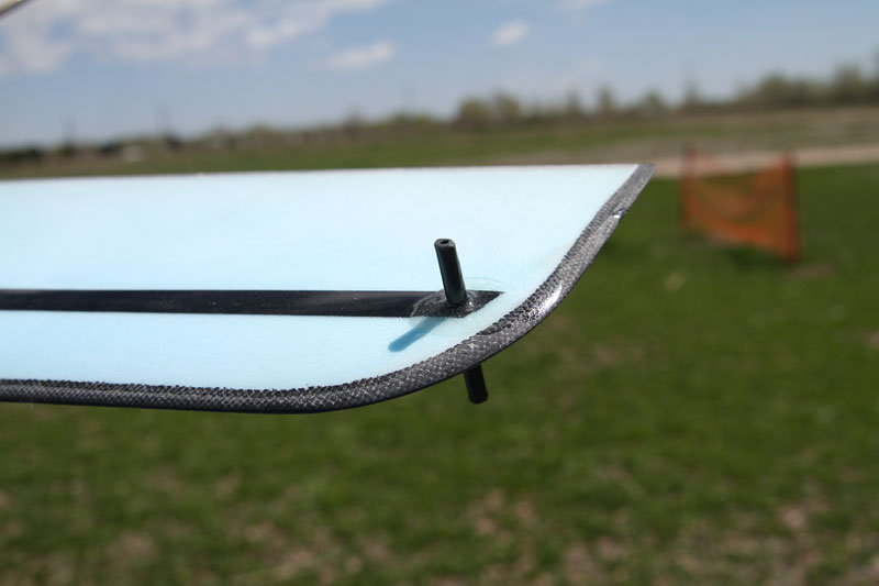
| Discus launch grip |
