YIPPEE!
By Glenn Smith Jr,
Bentprop Hobby Shop, ggsmithjr@gmail.com
[stextbox id=”black” caption=”SPECS” float=”center” width=”450″]
MODEL TYPE: Fan Fold Foam
SKILL LEVEL: Intermediate
WING SPAN: 54 in. (1372mm)
LENGTH: 48 in. (1219mm)
WEIGHT: 2 lbs. 15 oz (1332g) AUW
MOTORS: (2) AX 2850Q 750Kv
PROPS: (2) 3-blade FMS 9×6 counter rotation
ESC: (2) Turnigy AE-30 Brushless BEC
BATTERY: Turnigy 4S 2200mAh
RADIO SYSTEM: HobbyKing HK – T6A 2.4Ghz transmitter and receiver
SERVOS: (5) HXT 500 9-gram micro
FLIGHT TIMES: 5 to 6 minutes with the Turnigy 4S 2200mAh LiPo
[/stextbox]
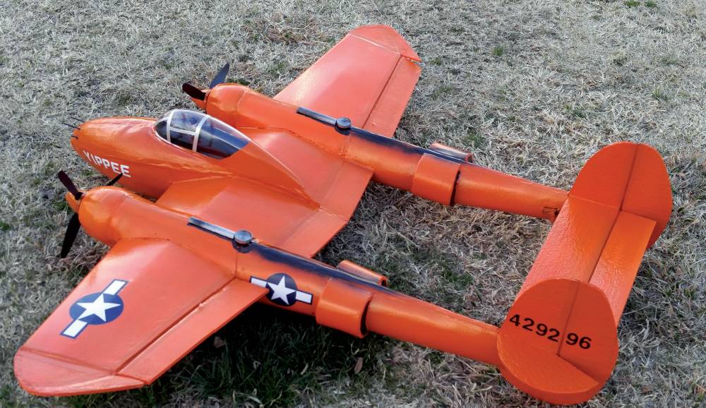
 Lockheed P-38J20 serial number 4423296 was rolled out of the factory in May 1944. This Lightning was the 5,000th example produced and it was a far cry from expectations of mere hundreds when the prototype was built in 1938-39. This latest P38 was painted a vermillion red and YIPPEE was applied under the wings and along the nose. YIPPEE was sent out on a publicity photo tour to boost the morale stateside during the tough times war always brings to the home front. After publicity photos were taken, the fighter was stripped of its manufacturer markings and sent out to the Pacific where it was desperately needed. At this point in the war, the P38 was still in high demand by USAA. Appropriately, YIPPEE was re-adorned in military markings and sent out to the only all P-38 fighter group operating at the time in the Southwest Pacific. The 475th Fighter Group acquired 4423296 probably sometime in June or July 1944 and assigned it to the 431st Fighter Squadron.
I have been using Fan Fold Foam (FFF) for over 10 years now in building model airplanes. In an effort to inexpensively construct a model, yet retain excellent flying qualities I have tried a variety of construction materials and techniques. FFF is an excellent material that can be very strong yet very light. I have perfected a system using FFF, Hot Glue and Masking Tape for construction. My most recent build is the P-38J YIPPEE! I kept track of building time with this one and I have a little over 10 hours from cutting the first foam piece to a model ready for flight! In this article I will share with you the process I currently use. YIPPEE is constructed as what we used to call a Stand- Off Scale model. There are deviations from scale in an effort to construct the best flying model possible, but in the air it looks “Real” enough!
CONSTRUCTION
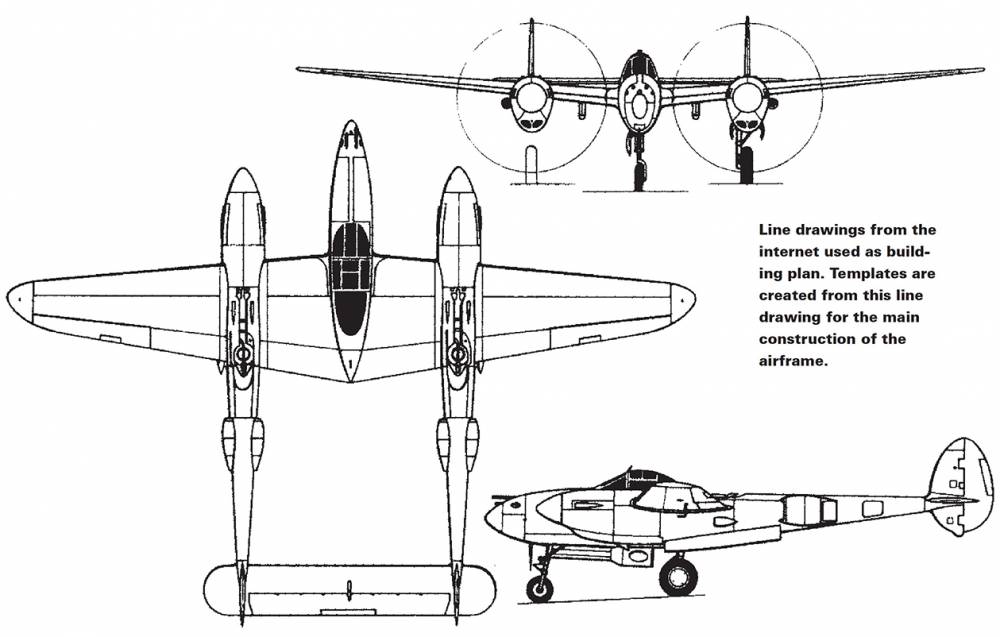
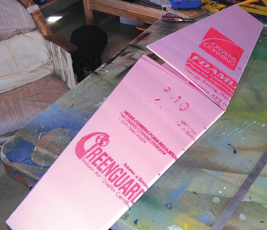
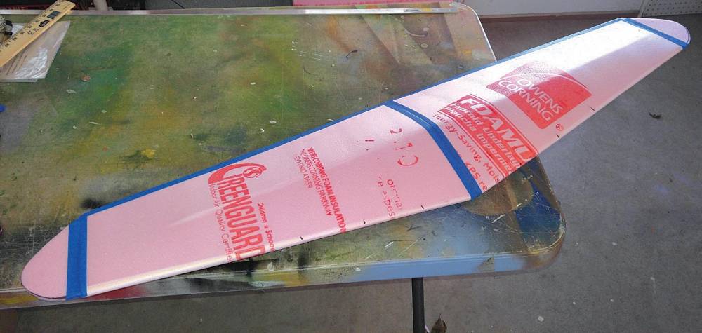
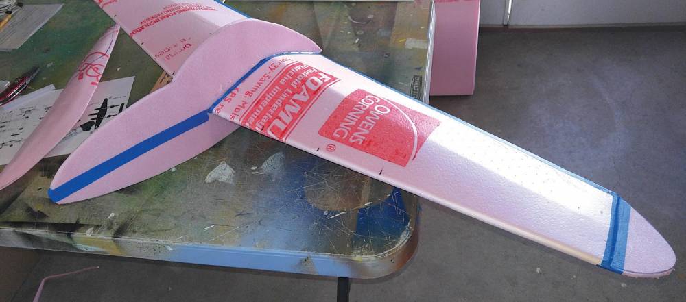
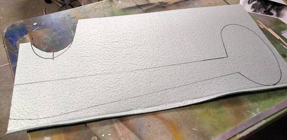
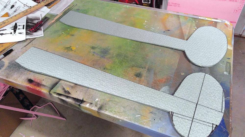
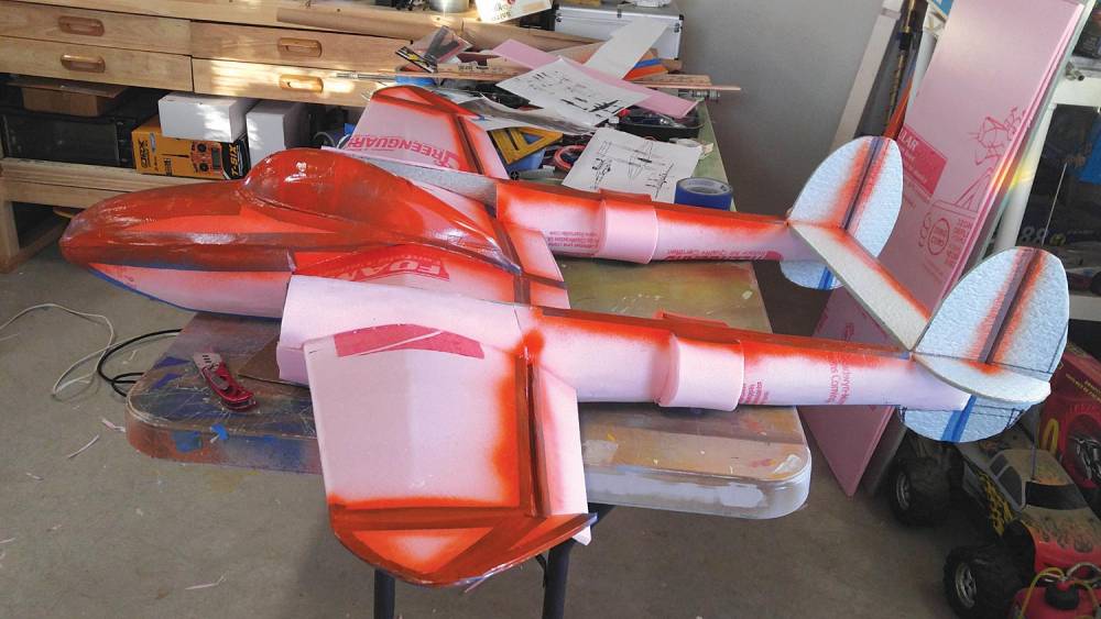
First, I printed line drawings from the internet for my plans. I have created a set of templates for the wing, fuselage keel and boom keels to aid you, should you decide to build your own FFF P-38. This project utilized three sheets of 2’x4’ FFF. YIPPEE is a scratch built project so be sure to draw all templates on the foam board before construction begins. In order to save time and weight I decided to go without landing gear. Yippee is so light, 2 lbs. 15 oz. ready to fl y, that hand launches and belly landings are a cinch! I began construction with the wing. In the case of the P-38, the wing is the main structural unit. Everything attaches to the wing, both of the booms and the fuselage, so beginning here is the logical first step. FFF comes in 2’x4’ sheets so I began by drawing out the wing on two sheets and cutting it out as the first step. By utilizing the folded edge of the FFF, a nice smooth wing leading edge is created. Cut the top and bottom of the left wing out separately from the top and bottom of the right wing. Then trim the center section to achieve the taper. At this point, glue the bottom skin of the left wing to the bottom skin of the right wing at the center section and let dry.
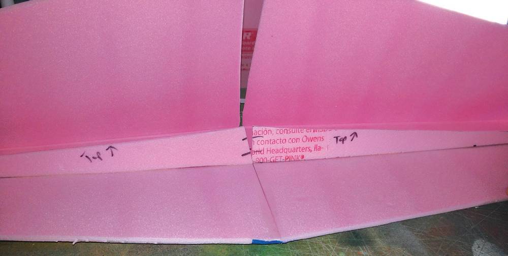
The next step is to cut out a spar and attach it, 1-3/4 “ thick at the center section tapering to 1/4” at the wing tip. The overall wing has a 14” chord and the spar is set on the CG which is located 4” back from the leading edge at the center of the wing. The spar is then hot glued to the bottom skin. Once that is set, the center of the spar is cut to achieve a 1-1/2 dihedral on each tip. The top skin will also need to be trimmed on the centerline to allow for the dihedral. Hot glue is applied to the top of the spar and the top skin is folded over and held in place until set. Once both skins are glued in place and the top skin at the center section is trimmed to allow for the dihedral, then apply glue to the spar and to one skin along the centerline. Fold together and hold/clamp until dry.
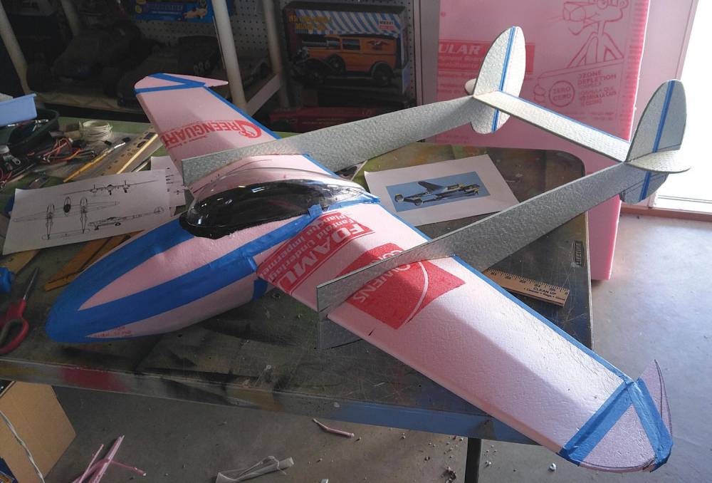
Once the spar is attached to the top and bottom skin and the wing is joined at the center section, hot glue is applied to the trailing edge and the top and bottom skin are held in place against each other until set. Masking tape is then applied over the trailing edge for added strength as well as on the center joint. Also, there will be a single sheet extension added to the wing trailing edge for ailerons and inboard flaps, which on this model will be stationary. Wingtips add another 3” to each wing and can be added at this point. This makes the overall wingspan 54”. Masking tape is applied to all glued seams.
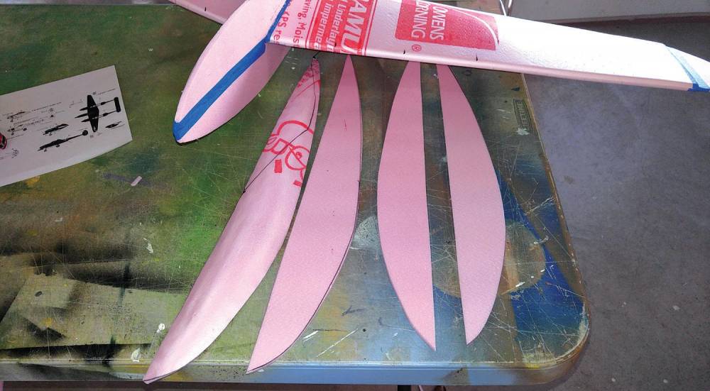
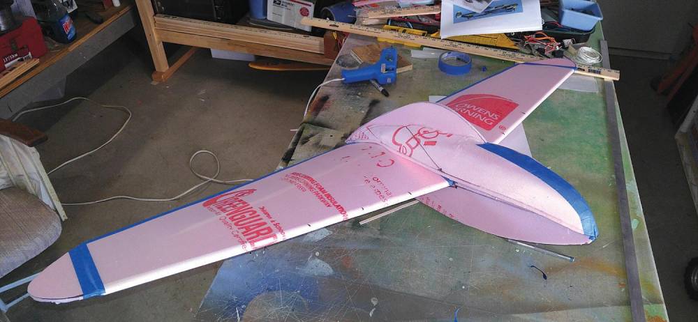
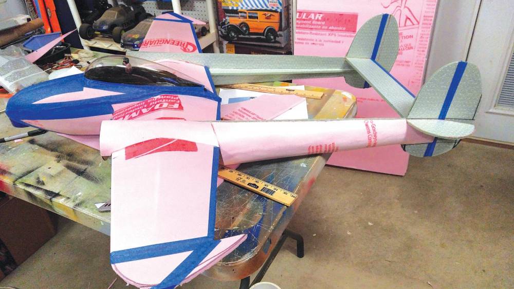
The skin foam is cut to fit and then hand manipulated to get the curved shape before gluing to the fuselage keel and formers. I have found it is easiest to cut the foam in 1/4” sections, applying them from the top of keel to former, then former to bottom of keel. These smaller sections are easier to hand form a curve in than trying to curve a whole side at one time. All throughout construction a close eye was kept with the line drawing to ensure that the model continued to look like a P-38! The same process was followed with the attachment and construction of the boom skins.

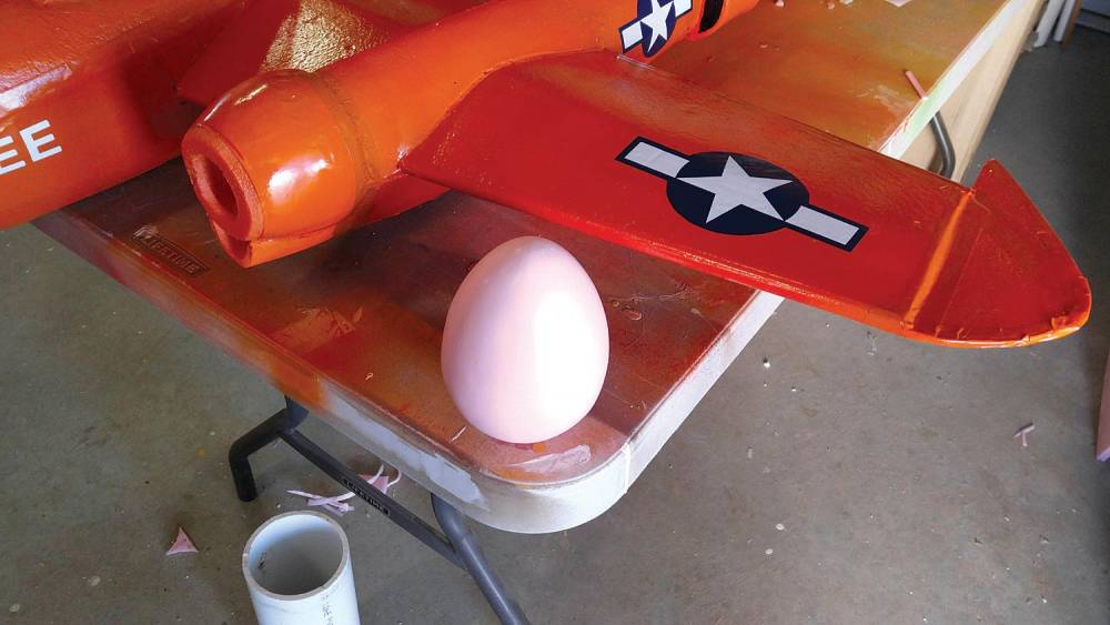
Engine nacelles were created out of foam easter eggs from Hobby Lobby! I cut off each end, then hollowed out the middle and cut a circular motor mount out to fit inside the nacelle. Cut your motor mount from 3/32 plywood. It will need to be “Cut to Fit” for whatever you use to construct the nacelles. I have used water bottles for cowlings and gun turrents, tupperware for engine nacelles and a host of other, off the shelf products to keep construction simple. Once the main construction is completed, two light coats of latex paint are applied to seal the foam and prevent any reaction of the foam from the chemicals in spray paint, which is used for the final color coat.
RADIO INSTALLATION
A HobbyKing HK-T6A 2.4Ghz radio was utilized with HXT 500 9-gram micro servos. Two AX 2810Q 750Kv motors were used along with two 30 amp BEC speed controllers. The props I used were 3-blade FMS 9×6 counter rotation and both required some modification by shaving the front and back of the hub to ensure a fi t on the motor shaft . I use a Turnigy 4S 2200mAh LiPo battery to power my P-38.All servos were installed as close to the control surface as possible and attached with hot glue.
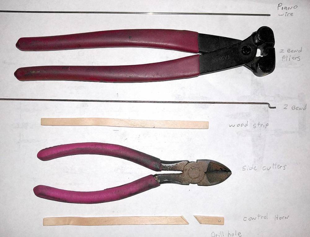
Control horns were made out of 1/4” x 5” craft sticks which come in a bag of 50 for $1.99. They were cut on an angle with a pair of side cutters and I used a Dremel to drill a hole for the push rod which I attached to the servo first, then to the control horn. This allowed for easy centering of the surface as the hot glue used for the control horn dried. A slot is cut with a hobby knife into the control surface for the control horn to slip into and a dab of hot glue is added over the slot. Once the control horn is pushed through the hot glue it will attach both to the inside of the foam surface and the outside. This makes for a really nice, strong control horn.
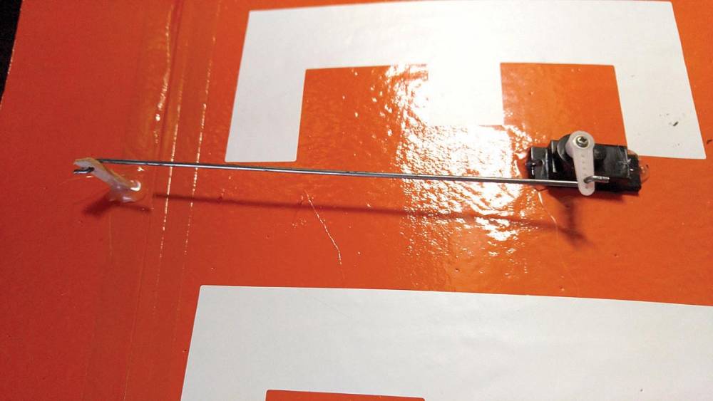
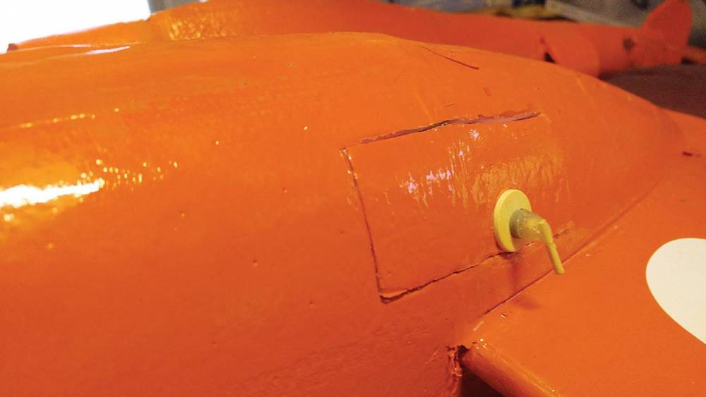
Since the formers on the booms run the length of the keel, servo wires were fed from the servo up to the forward area of the wing spar. An opening can be cut in the top of the wing skin, under the top boom skin which you have not attached yet to allow for this step and then the wires can then be fed down the hollow wing to the fuselage. ESC wires can follow suit through the wing opening to the fuselage. Cut the radio access hatch on the side of the fuselage under the wing. Through this hatch you can cut an opening in the bottom wing skin for all wires to come thru and plug into the receiver. Cut the hatch large enough for battery access as well. The battery can be positioned into the forward fuselage and set so as to achieve the proper CG on the wing spar as described earlier. Aileron servo wires will easily run through the wing to 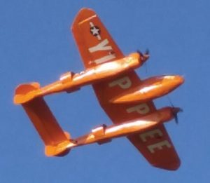 the opening created in the bottom wing skin inside the fuselage. Be sure to install the aileron servos in front of the wing spar, otherwise the wires will not come out inside the fuselage at the hatch opening. The application of decals (Stars and Bars) and super-chargers, which were made out of a split dowel stick with a 3/4-inch wooden craft disk, all available at Hobby Lobby, and nose guns made from wooden shrimp skewers, all add to the overall look of YIPPEE! A splash of black spray paint creates the “Exhaust Gas Singe” look! In the air she is a dream!! It is a very docile, very easy flying machine. Rolls are effortless! The two 2810’s provide plenty of power and most cruising around was done at 60% power for some very scale looking flight!
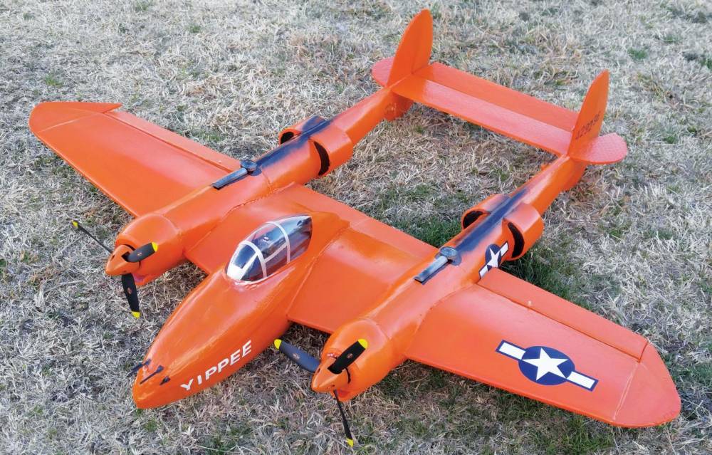 All in all, a very successful build and fun flying airplane. FFF puts the ownership of many of these great airplanes within reach of everyone! All that is needed is a little time and effort. I began by building simple one-sheet profile airplanes and gradually moved up to more detailed designs. I have a BV 141, ME 110, Rare Bare and a host of other models constructed this way. With some simple electronics the total cost of YIPPEE is well below the $100 mark, which makes it a very affordable weekend fl yer! If you haven’t tried FFF, now’s the time. The only limit to what you can create is your imagination alone. Blue Skies! Be sure to check out the digital edition for downloadable plans.
 Fly RC Magazine WE LIVE RC
