This month’s column is based on Building the Stinson SR-9, blog No. 12, on www.rcmodel.com. For direct access to all of my blog entries on this (or any other) project, go to the archives tab partway down my home page and click the appropriate subject under catagories.
I haven’t been able to add as much as I’d like to the Stinson SR-9 story recently. Let’s just say that life has been really generous in providing me with things to do that don’t include model airplanes. However, there are LOTS of neat things going on in my shop, among them slow but steady progress on this airplane. Let’s get back to work.
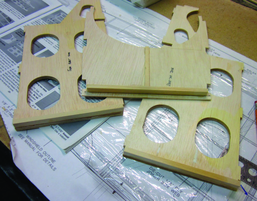
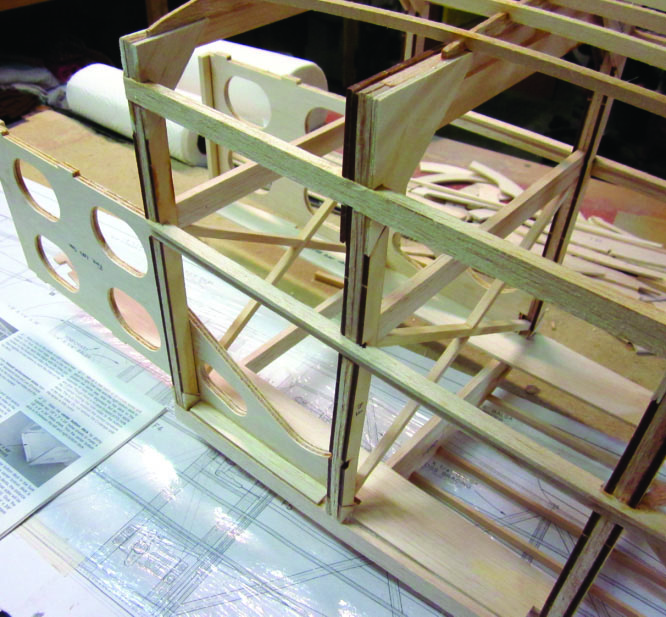
During the last blog post on my website, I showed you how the Stinson kit design requires you to laminate several components of the nose structure (the fuselage ahead of former F-3, which lies in line with the leading edge of the wing) from die cut 1/8 inch plywood components and then to add various basswood strip spacers. These ensure that the firewall (F-1), which serves to define and lock in the angles at which the motor mount structure will relate to the rest of the airplane, will end up exactly where it is supposed to be. These angles define sidethrust and downthrust offsets, which are critical to building a good-flying airplane. By designing discrete offsets into the structure rather than leaving them to be determined by the odd shim or spacer later, the designer has added real value to this kit.
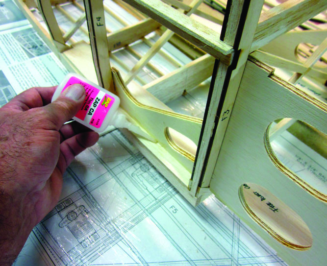
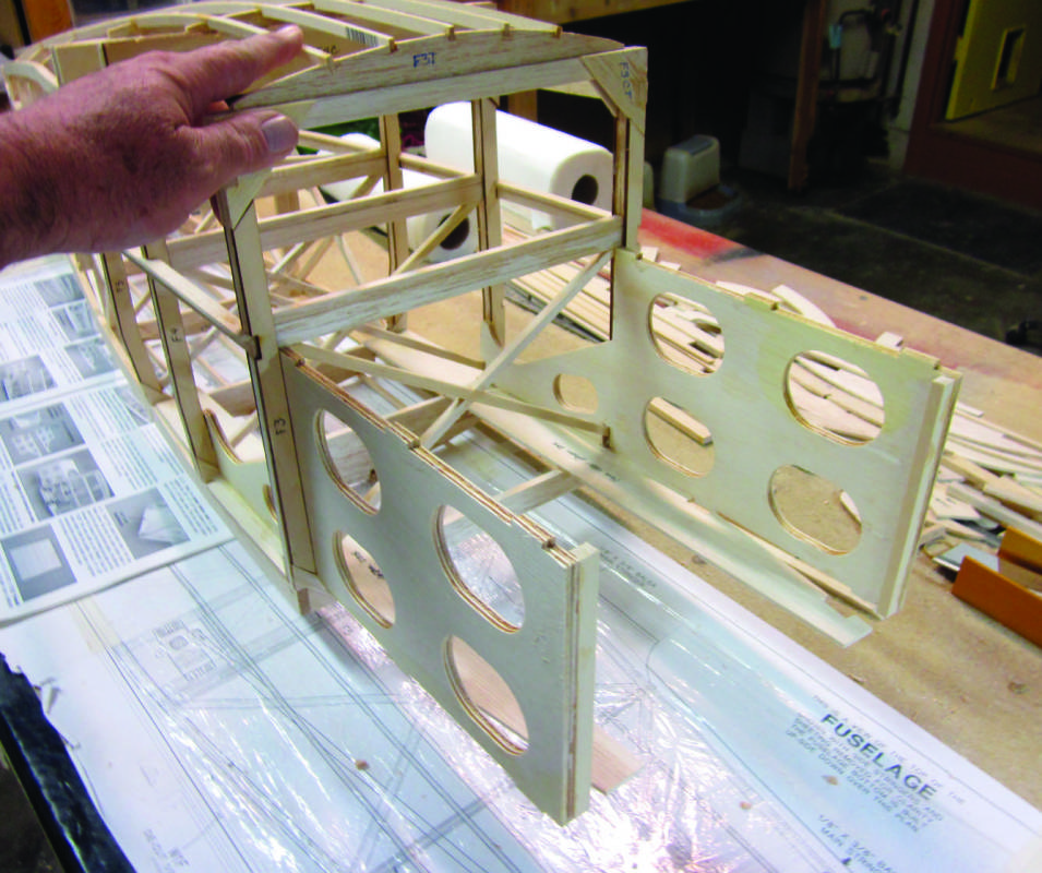
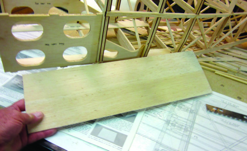
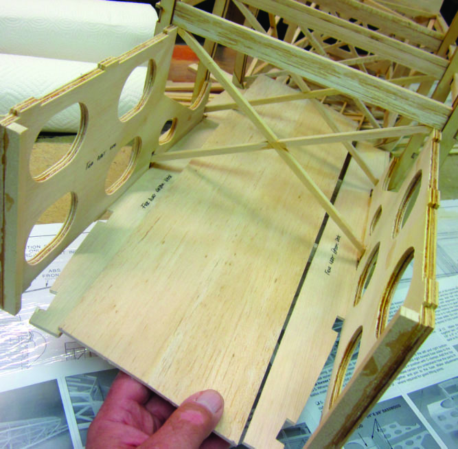
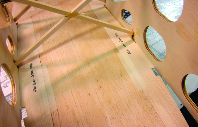
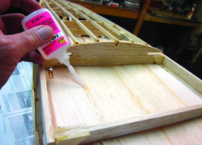
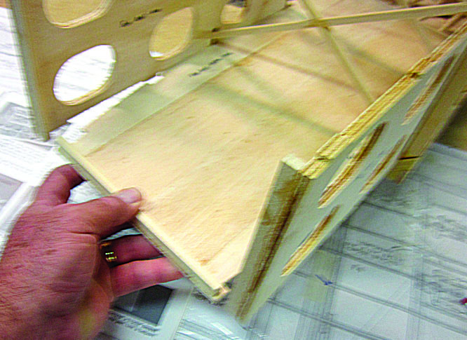
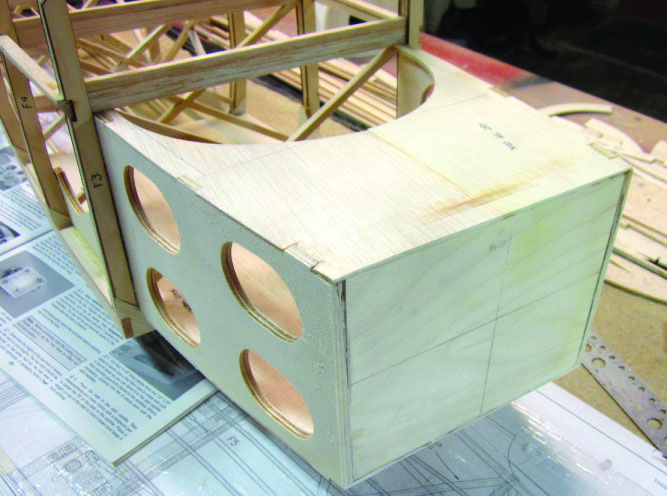
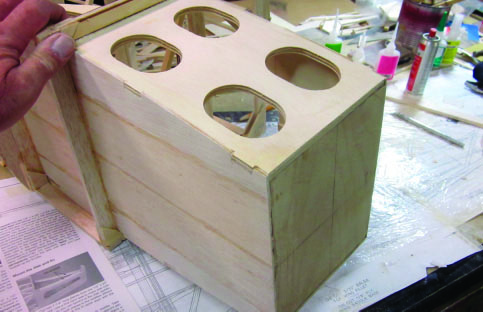
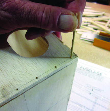
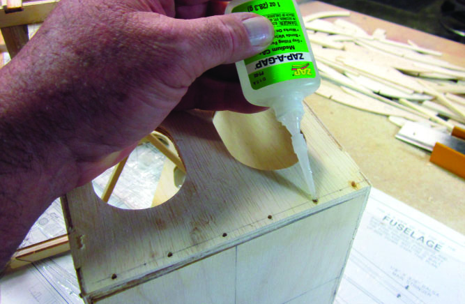
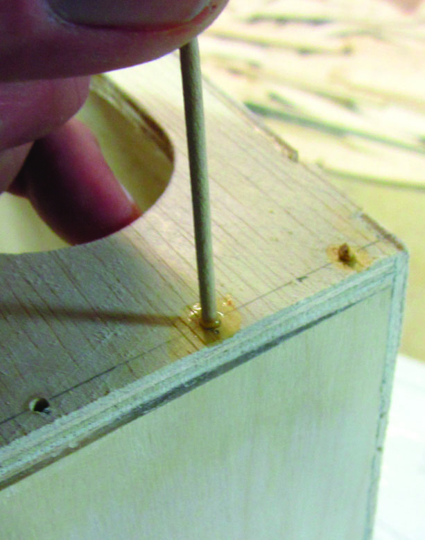
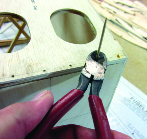
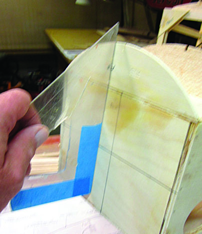
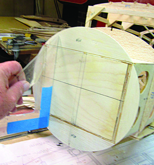
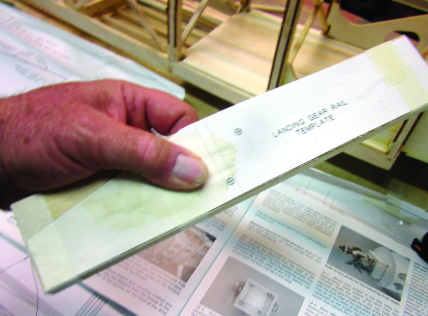
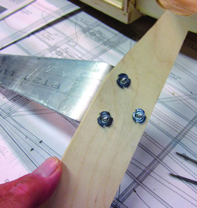
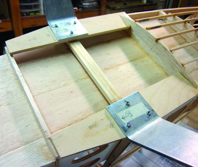
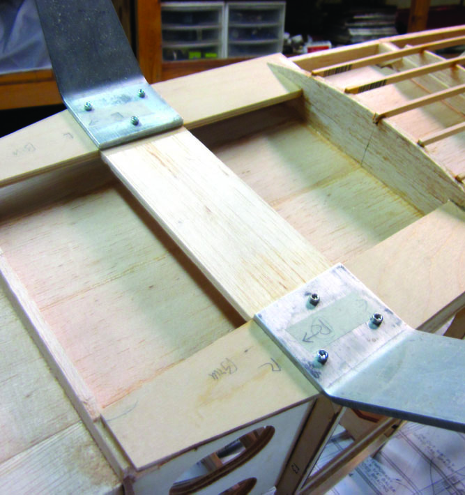
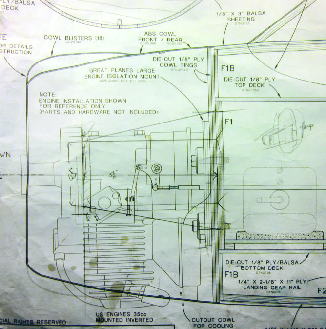
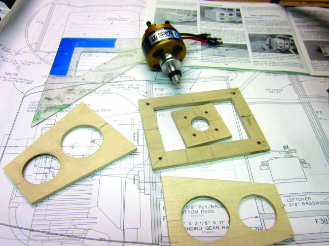
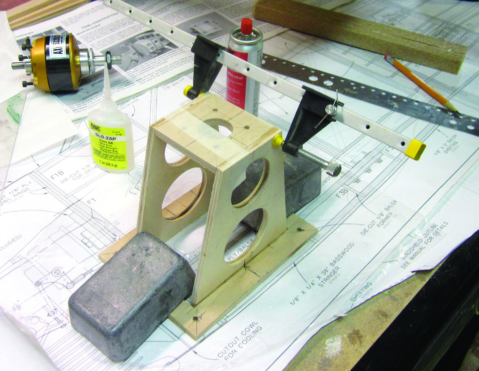
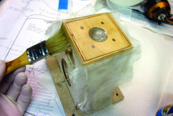
These basswood spacer rails are offset from the front edge of each of the forward fuselage sides at just the correct distance to form a pocket into which the firewall (F-1) will fit.Previously I testfitted the assembled right and left forward fuselage sides and trimmed as necessary to be sure they fit accurately into the structure between F-3 and F-4. Now I have them fitted into place and double- checked for accurate alignment. I used fast (thin) ZAP for this job in order to be able to pre-assemble everything “dry” and THEN apply adhesive to each section of the joint.Here both forward fuselage sides are in place; ZAP’d securely at F-3 and F-4. At this point they are still parallel.The bottom center deck consists of two 1/8x3x24 inch balsa sheets edge-glued and trimmed to fit into the open space left between the right and left bottom deck pieces.Both the right and left bottom decks are in place here, against the bottom longeron and the inner faces of the forward fuselage sides. So far there’s no adhesive on them ahead of F-3.I’m test-fitting the center deck to make sure I’ve got it right before I reach for the ZAP.This is the bottom deck assembly with the center deck ZAP’d in place as seen from above.I turned the fuselage upside down and gave each of those long edge joints in the 1/8 inch balsa sheet deck assembly an extra shot of ZAP to make sure there were no dry spots left in the glue joints.The next step is to glue a 1/4×3/8 inch basswood strip across the front of the deck assembly. NOTE: When this crosspiece is in place, in alignment with the 1/4×3/8 inch basswood vertical members on the side assemblies, the forward edge of the deck will form a lip ahead of it…the firewall (F-1) will fit in here soon.While the camera wasn’t looking I pulled the fuselage sides in to fit against the bottom deck assembly, added the top deck, and slipped the 1/4 inch plywood firewall into place in the space the parts in the last step defined when they came together. Because the right and left sides are of different lengths, (in order to provide side thrust offset) this assembly is NOT SQUARE as viewed from above. This is where you have to trust the die-cut fuselage side parts to be RIGHT and then double check the offset assembly against the fuselage top view on the plan before committing it all to the ZAP bottle…or before the epoxy sets if you’re going that route. Here I have already removed the various clamps and braces I used to keep all that stuff under control.Here’s another look at the same nose assembly as seen from the underside.The kit instructions suggest that you “pin” the four joining edges of the firewall and I concur. Here I have drilled a series of holes through the top, side and bottom pieces about 1/2 inch into each edge of F-1 sized to accept an ordinary round toothpick pushed firmly into place.I want to be absolutely sure of complete glue penetration into each “pin” hole so I’m filling each one in turn with slow setting ZAP-A-GAP before inserting the toothpicks.Each toothpick “pin” gets a firm push to seat it all the way into the waiting ZAP-AGAP adhesive and fill the predrilled hole.I used a pair of side cutters to trim off each pin close to the surface. A few minutes with a sanding block will finish cleaning up the assembly.Now it’s time to add some roundness to the nose. I have already added F-2 Top and both F-2 Side formers and here I’m using a square to align the upper F1B with the top of F-1 (the firewall).The lower F-1B and both of the F1S formers go in place next. Adjust these former sections as necessary with your sanding block to be sure their outer edges form a smooth circle without steps or bumps. That outline is going to define the shape of the nose where it fits the engine cowl and it will show.With any full-scale building or restoration project, getting the airplane “on the gear” …having the landing gear structure support the weight of the airplane for the first time…is a big deal, if for no other reason that it sure makes the fuselage easier to move around the shop. The same goes for our models when they get this big. I got started on this part of the job by cutting the paper landing gear rail template from the plan and using it to mark out two landing gear rails on 1/4 inch plywood.I drilled both L.G. rails per the template for the 6-32 bolts that hold one landing gear strut to each of them, and put together one RIGHT and one LEFT strut rail assembly. If you don’t get the blind nuts installed securely NOW on what’s going to be the inside face of the rails, you’ll never be certain they’re right.With the main gear struts bolted in place as an aid to alignment, I added the strut-rail assemblies to the fuselage with plenty of ZAP-A-GAP.When that adhesive had set up hard, I added the landing gear brace across the bottom of the fuselage between the rails.Next comes the motor mount. The TOP FLITE kit was designed for glow or gas engines and there is no reference to electric power anywhere on the plans…but…we already know it’s going to work so the only added task I have to face here is figuring out how to mount the motor I’m going to use. At this point I need to explain that there aren’t any photos of this part of the build as there might be. Caught up in the challenge of designing and building an adaptor mount the “old time model builder” in me took over and got lost in the drawing-cutting-gluing process without reaching for the camera as often as the website blog-teacher part of me would have liked. That operation began with my “pencilling in” some basic dimensions right on the existing fuselage side elevation of the kit plan. I left this as-is to reveal just how intuitive stuff like this can become when you get some experience working out model airplane structure on your own. Those faint pencil marks and some measurements with a ruler are all I worked from.There weren’t any patterns…I took measurements off the sketch I made on the plans, drew dimensions directly onto 1/4 inch plywood in pencil, and then cut it all out on those lines. The lightening holes were made with a hole saw mounted in my drill press. The overall length of the motor mounting box is determined by those two trapezoidal side frames. I got the necessary dimensions by copying the outline of my AXI 5320 motor onto the plan, determining the distance that would need to be filled in between the mounting plate and F-1, and reflecting that measurement in the length of the frames.I assembled the motor mount with 30-minute epoxy, using the devices you see here to square it off and keep it that way while the epoxy cured. Then I drilled and set toothpick pins into every joint just as I did with the assembly of F-1 into the fuselage.All the work I did earlier to make the wheel pants fit right is going to pay off now. I know this one is going to slip into place without my having to scuff up that nice new paint job.
SUMMARY
Next time I’ll let you have a look at the finished box all cleaned up and mounted on the airplane with the motor in place…which is where I’m going to need it to begin fitting the cowl. That’s all we have room for here, but there’s more. Go to http//:www.rcmodel.com/2012/10/ building-the-stinson-sr-9-12/ to see all the rest of the details of Stinson blog No. 12.
 Fly RC Magazine WE LIVE RC