 Fly RC Magazine WE LIVE RC
WHAT IS WASHOUT AND WHY BOTHER WITH IT AT ALL?
Washout is a spanwise twist in the wing that reduces the angle of attack at the tip in relation to the root and is used to avoid tip stalls in turns and when flying near stall speed. (Note the tip washout detail drawing on the downloadable plans at HERE.) When an airplane is in a turn, the turning radius at the wing tip on the inside of the turn is flying slower than the tip at the outside of the turn. As a result, if the model gets too slow, it can tip stall and spin into the turn. If the model is too low, the spin can’t be recovered and the model will crash—and we don’t want that!
HOW MUCH WASHOUT IS REALLY NECESSARY?
After many years of experimenting with washout, I have found that 1.5 degrees is a good average. With too much washout, the model will tend to “fall into the turn,” and will act a little funny in straight and level flight as well. With too little washout, it will be more prone to tip stalls, especially on models with higher wing loadings. In addition, when building fast airplanes, too much washout will create excessive drag and can severely limit the speed.
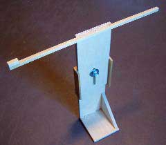
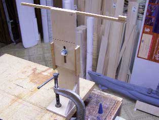
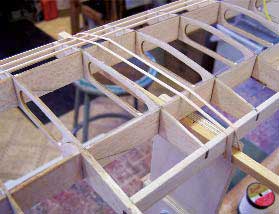
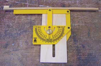 1 I used an angle gauge to align the upper beam and to ensure the 1.5-degree angle is accurate on the outer stanchions. |
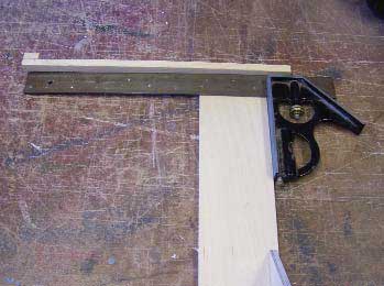 2 A machinist’s square will ensure that the upper beam is perpendicular to the vertical edge on the inner stanchions. |
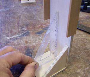 3 A drafting triangle helps align the base with the vertical support. The support gusset is then glued in place. |
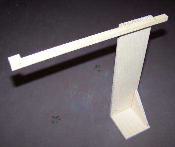 4 The completed inner stanchion is ready to mount on the building board. |
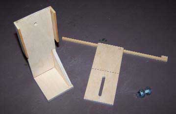 5 Here are the unassembled components for an outer stanchion. |
 6 The completed outer stanchion is ready to mount on the building board. |
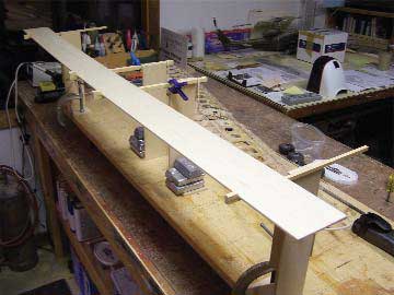 7 Use a long straight edge to align the leading edge stops; then, secure the stanchions to the building board. |
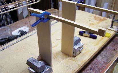 8 I use lead weights to anchor the inner stanchions to the building board. They can also be screwed or clamped in place. |
 9 I use C-clamps to hold the outer stanchions in place. |
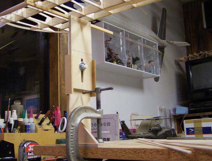 10 With the stanchions secured to the building board, set the model into the jig.
BUILDING THE WASHOUT JIG
The idea in building the washout jig is to develop a system that is universal enough in form to set up models of varying sizes and configurations such as straight or swept leading edges. It is also set up to adapt easily to wings of varying dihedral. Since the vast majority of the models I build use a flat bottom airfoil, I have designed the basic jig for use with flat bottom airfoils. Adapters for specific sizes and types of airfoils can be built easily and used with this basic jigging system.
The jig is not difficult to build, but care must be taken to ensure that the support beam angles are set up properly for it to be effective. Medium CA and accelerator were used to glue the components together.
Construction begins by cutting out the 1/4-inch ply parts using the full-size templates provided. Make up the beams for the inner and outer stanchions from nice, straight 1/4 and 3/8-inch square spruce. Cut the 1/2-inch long leading edge stop blocks
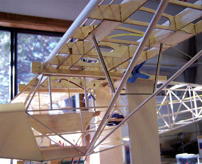
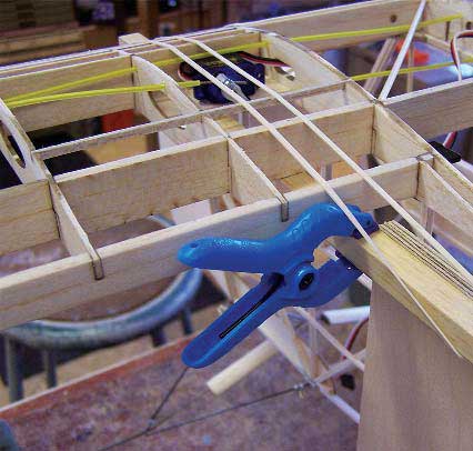 12 I use small spring clamps to hold the wing against the leading edge stop blocks and rubber bands to hold the wing securely against the alignment beam. 12 I use small spring clamps to hold the wing against the leading edge stop blocks and rubber bands to hold the wing securely against the alignment beam. |
 13 Adjust the outer stanchions to the proper height to set up the wing dihedral angle. |
 13 A rubber band secures the wing at the outer stanchion alignment beams to set the proper washout angles. |
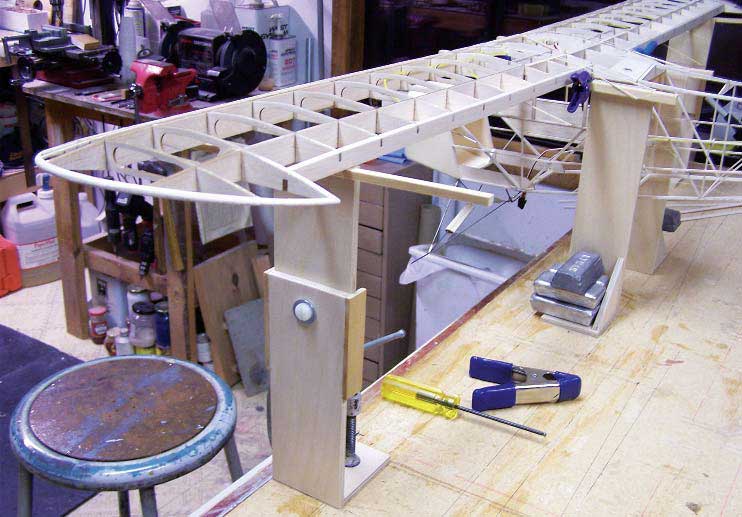
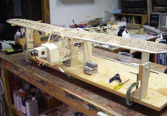 14 With the model fully secured and jigged, I am ready to set up the lift struts. |
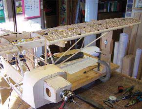 15 The jigged model lets you establish the lift strut length and install the struts so that they are not ‘loaded” by being too long, or too short. |
16 While the model is still in the jig, I fit and installed the jury struts. Again,
fit the struts carefully to avoid any “pre-loading” that can spring the wing out
of rig when the model is removed from the jig.
Starting with the outer stanchions and using a triangle to ensure proper alignment, glue the base and base gussets in place on the lower upright, part #2. Glue the vertical centering guides in place next, and then sand the upper section 2A until there is a nice smooth fit in the guides. Glue the 1/4- inch square beam assemblies in place on the upper section as shown and use an adjustable angle gauge to ensure the 1.5- degree angle is correct. Assemble the upper and lower sections using a 1/4-20 x 2-inch nylon bolt cut down to 11/2-inches long and with the nuts and washers as shown.
Assemble the inner stanchions starting with the base and base gussets, followed by the 3/8-inch square beams. Use a machinist’s square to ensure the beams are perpendicular to the vertical edges. With the stanchions finished, it is time to set up the jigging system for your specific project.
USING THE WASHOUT JIG
I used an 18×48-inch particleboard base to support the stanchions. The spacing between the outer stanchions is determined by the wingspan of the model being jigged. Secure the stanchions in place at the front edge of the board using either screws into the base, or C-clamps. The inner stanchion spacing is determined by the width of the fuselage. If your wing does not sweep, use a straight edge to align the leading edge stop blocks and secure the inner stanchions either with screws into the base or with lead weights. Be sure that the spacing between the inner and outer stanchions is equal on both sides.
The next step is to secure the model into the jig using rubber bands across the beams and over the wing at all four positions. With the model secured in the jig, you can set up the struts, knowing that when the model comes off the jig, the washout and dihedral will be exactly right.
CONCLUSION
That’s all there is to it. I didn’t permanently attach the stanchions to the work board, so the jig can be used again on different types and sizes of models. It might seem like the jig is a bit time consuming to build and set up; however, once you get used to using it, the time spent setting up the jig will be far less than the time spent actually rigging the model if the jig were not used, and the results are likely to be much more accurate.
Editor’s note: Pat Tritle is well known for his many designs published over the last 35 years. His designs are noted for their light weight, and exceptional performance and realism in flight. We are honored to include this feature in Fly RC, and are confident that the use of this jig will improve the accuracy of your next model.
