 Fly RC Magazine WE LIVE RC
Fly RC Magazine – June 2012
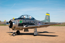
Airfield RC T-28 Trojan ARF EP
Scale looks and detail in ARF form
By Mike Lee
Photos By Mike Skube and Mike Lee
AT A GLANCE
MANUFACTURER: Airfield RC
DISTRIBUTOR: NitroPlanes
TYPE: Scale, electric powered ARF
FOR: Sport and Intermediate pilots
PRICE: $253.99
NEEDED TO COMPLETE:
6-channel radio system, 14.8V 2600mAh LiPo battery pack
ASSEMBLY TIPS
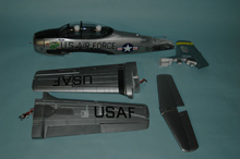
The main material used to create the T-28 is molded EPO foam. And while this particular foam is capable of accepting many different types of adhesives, I do not recommend the use of CA type adhesives. This is due to the molding process that seems to seal the surface of the foam and prevents adequate penetration of the adhesive into the foam, resulting in a weak joint. The hardware outfit does include a tube of foam compatible contact cement, and it does work fine.
The wing goes together first, and when you bring the wing halves out of the box, you might just panic a bit. You’re going to see a BUNCH of wires at the wing root, coming from the following items; Aileron, Flap, Landing Gear, gear door, and navigation lights. Stay calm because they are all labeled for where they go when connecting to the receiver.
The two wing halves are joined using two fiberglass joiner tubes and then held together with two plastic joiner plates. It is a very tight fit at center, so you need to work carefully to get the wings properly mated squarely. I suggest immediately mounting the wings to the fuselage and bolting them in place as per the instructions. This will do two things for you; it allows you to work on the plane with the landing gear deployed, and it allows the wing to settle into position, making the wing mounting chore much easier in the future. Once the wings are in place, sort through the maze of wires to connect up with the receiver.
You will have to install the pushrods from the wing servos to the control surfaces, which is not a problem, however, I do suggest doing a “break-in†on the ailerons and flaps. Both are live hinged using the native foam material, and are quite stiff from the factory. Flexing them vigorously a few times will help a lot. I also suggest that you move forward with hooking up the radio system to the ailerons and flap to get the servos centered up prior to fitting up the pushrods.
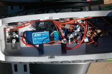
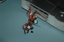
In our example, we employed a JR R921-X receiver, featuring the JR DSM-X signal format. Calling the shots was a JR 11-X transmitter. While it is not necessary to use a high end radio system, the 11-X makes the system set up very fast and easy. There is plenty of room inside the fuselage for radio gear, so take your time. And the wire maze gets easier. The kit provides specialized wire connectors to allow you to consolidate the individual wing and control surface wires into single connections to the receiver. For the retracts and gear doors, the kit provides a retract amplifier with gear door sequencer. All the retract wires plug into the connectors on the amplifier, as do the retract gear door servos. Once plugged in, suspend the model above the workbench and clear of anything that may be in the way, and hit the retract switch on the transmitter. If you did everything right, the result is a beautifully coordinated gear down sequence!
As you work forward, you will find another specialized wire connector that hooks into the wing and cowl flaps. Yes, there are cowl flaps! Once the flaps are connected up, a command from the transmitter will deploy the flaps in slow, 3-second movement. Do not try to set up variable flaps on a slider switch from the transmitter, as the flap amplifier is set for either full up or full down only. Moving along, we note that the navigation lights are connected for constant power as long as the battery is connected. The wing lights are always on, but the fuselage beacon lights flash. Pretty cool!
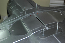
Going on back to the tail section, you need to place the horizontal stab onto the vertical fin and then mount the completed assembly to the fuselage. This is a very snug fit that leaves no slop, and so you need to work patiently to get the fit correct. The patience will be worth it, as the joints are tight and clean. Make sure you use an adhesive that allows you some working time for best results.
Once the tail surfaces are mounted, you start hooking up the pushrods to the rudder and elevator. The elevator uses a split “Y†pushrod to allow separate trim of each elevator half. It was at this point we ran across our first (and only) real problem. The kit supplied hardware for the control horns contains both long and short self tapping screws in order to penetrate and reach through the thick control surface. Be aware that the short screws are simply too short and will not reach the anchor plate. I replaced my short screws with 2/56 machine screws cut to length. Note also that the pushrods for both rudder and elevator are held to the servo by “quick connectors†and use a set screw to hold the pushrods in position. It is a wise move to make sure they are fully tightened down.
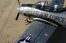
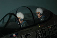
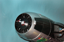
At this point, we have a fuselage with wings and tail sections attached, leaving us to the nose and canopy. The powerplant is 4250-kv500 outrunner motor, mated to a 50-amp ESC. The motor resides behind a dummy radial engine that would not take much to detail out for some nice realism. There are several vent holes between the dummy cylinders for fresh air intakes. Included with the Trojan is a scale 3-blade prop done up with a chrome polished hub and metallic blades. The prop measures 13-inch with a 9 inch pitch. Up in the nose area is also the only piece of hard plastic that you need to glue, this being a vent cover along the bottom of the cowl. Lastly, we have a large canopy cover that snaps into place quite securely. Inside the canopy are two completely painted pilot figures, both facing a full instrument panel.
The only thing left to add is the 4S LiPo battery pack. I installed an E-Flite High-Power series 4S 14.8V 2500mAh pack, which fits perfectly in the battery bay. There is actually room for a larger capacity battery, if you desire, and it will not affect the balance of the Trojan as the battery sits right over the CG. We now have a completed model and it’s time to perform a complete operational systems check. My model checked out perfectly the first time and I then set up the control surfaces for the following control throws:
Aileron: 5/8†up/ 5/8†down
Elevator: ½†up/ 3/8†down
Rudder: 5/8†left/ 5/8†right
Flaps: 45-degrees down.
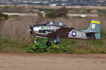
The completed ready-to-fly weight of the Trojan came out to 95 oz, which translates to a wing loading of 26 oz/sq ft and a wing cube load of 13.4, based on a calculated wing area of 529 sq inches. Although this sounds a bit heavy, it truly is not due to the thick, high lift wing section mated to a fully airfoiled tail section. The motor tested out to produce 476 watts of power at 5,700 RPM. This equates to a modest power to weight ratio, which should produce a very scale flight speed. (Don’t forget this is a scale basic trainer and not a purpose built fighter plane.)
Image Gallery
 |
 |
 |
 |
 |
 |
 |
 |
 |
 |
||
Links:
Horizon Hobby
E-Flite
JR
Nitroplanes
