 Fly RC Magazine WE LIVE RC
By Bob Benjamin
A while back I wrote a two-part article in Fly RC magazine explaining how I scaled out the big 1/6-scale WACO SRE ARF from SIG. That article was essentially about getting rid of the plastic covering, getting the servos inside where they belong on any self-respecting scale job, and messing with the overall appearance by adding things like scale tail surface cross sections, fuselage stringers, door outlines and the like. I also added a dummy scale nine-cylinder radial engine, a detail that is overlooked in the ARF kit. Between the shape of the cowl and a big propeller spinner, you don’t see a lot of it, but having it there makes a difference you can’t miss. I lost count of how many times I was asked where I got that dummy engine at the flying field. I decided to include a blog entry on Bob Benjamin’s Old Time Model Airplane Workshop on my website at www.rcmodel.com.
This article is based on material developed first for my website, and like the rest, there’s more to it than our editor has room for in any realworld page space allotment. Well, as a confirmed hard-case scale nut, I hate leaving out any of the good detail stuff.
Step 1.
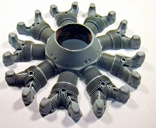
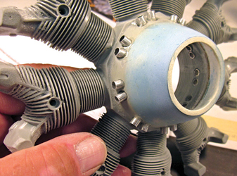
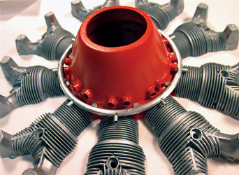
This is the generic 9-cylinder radial engine casting as it comes from Frank Tiano Enterprises (FTE). It is not actually a Wright, or a P&W, or a Jacobs, or anything else, but you can finish it up to look convincingly like any of those well enough to suit the needs of anything short of a Top Gun caliber airplane.
Step 2.
Same deal from the back. Notice that there are some small lumps, bumps and molding imperfections, you can clean that stuff off yourself, to the standards you set. These basic castings come in several sizes. This one is 1/6-scale. I have read reports of modelers using these in glow or gas powered airplanes feeling the need to reinforce the back of the casting with light plywood to prevent cracking off of individual cylinders from vibration. As I fly exclusively electric power, I have not encountered that issue.
Step 3.
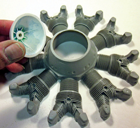
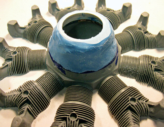
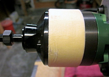
I’m way out on my own here. The front of the stock crankcase is cut off a bit short and opened up to accept the front end of just about any engine or motor you might want to use. It turned out that the Cobra outrunner in my Waco SRE would fit snug up inside the casting with a fair bit still protruding out the front, so I decided to make a custom add-on to represent the front end of the reduction gear housing of the full scale engine, using part of an old plastic spinner. (I don’t remember what size; I found something from the junk box and cut it off on the band saw to fit the engine casting.)
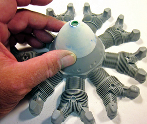
Step 4.
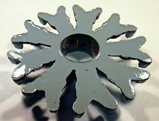
I sanded the front face of the engine casting nice and smooth. If you do this mod, the cutoff point for what’s left of your old spinner has to be chosen to match the front of whichever FTE engine casting you have.
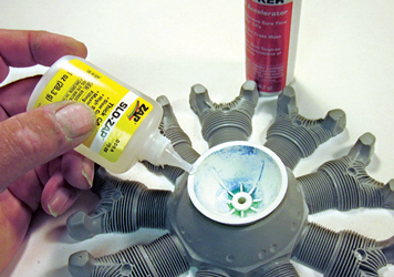
Step 5.
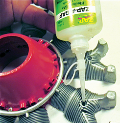
I used SLO ZAP to glue the cut-off rear edge of the spinner to the engine casting. (I’ll turn the spinner portion over once the glue line is in place.)
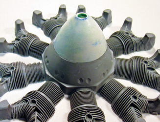
Step 6.
The fake front from the old spinner is cut to size and securely ZAP’d in place.
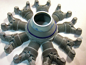
Step 7.
With the assembly glued up, I was able to measure accurately how much needed to be cut off the front to get an exact fit with my working motor. Here I’ve done that and marked along the rear edge of the reduction gear housing (the front of the dummy engine) just how far back I’m going to go with epoxy filler.
Step 8.
The contour formed by the junk spinner and the epoxy crankcase isn’t just right, so I added some filler using Stits SuperFil.
Step 9.
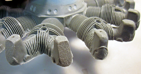
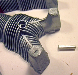
The dummy engine is going to be mounted by the valve covers as part of the cowl. As this is not an exact scale representation, the fit between the cowl and the engine is not perfect. In an ideal case we would build small brackets to attach each valve cover to a mounting ring inside the cowl; however, in this case each of the dummy valve covers needs to be cut back about 3/32-inch with coarse sandpaper to fit where it belongs. As this part of the engine is going to be permanently hidden, that doesn’t hurt anything.
Step 10.
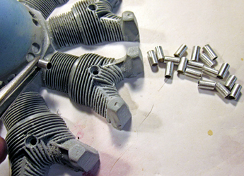
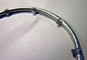
On the full scale radial engine, the cam rings are located inside the portion of the crankcase just ahead of the cylinder attachment flats. Using reference photos for the engine I am representing, I made locating marks for each pushrod housing base (eighteen, since this is a nine cylinder engine and each cylinder has two valves and thus two pushrods.) I used short pieces of 3/32-inch aluminum tubing from the K&S rack at the hobby shop, cut the required number to length, and drilled holes in the crankcase to accept them.
Step 11.
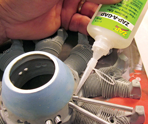
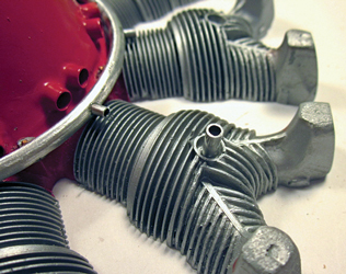
Each pushrod tube base is glued into its own hole using ZAP-AGAP. As each one is positioned in turn I aligned it with a piece of pushrod tube slipped into place. Note that on this engine (a P&W R-985) each pushrod tube emerges from its base at an angle, slanted back toward its respective cylinder.
Step 12.
Here you can see the crankcase front all sanded to final shape with the pushrod tube base holes drilled and the base tubes assembled.
Step 13.
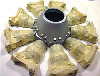
The parts of the engine that are assembled so far are the ones that are going to be painted, everything else will be bare metal or rubber. I have sprayed the entire engine casting silver using my favorite Stits Polytone and masked off each of the cylinders prior to painting the crankcase.
Step 14.
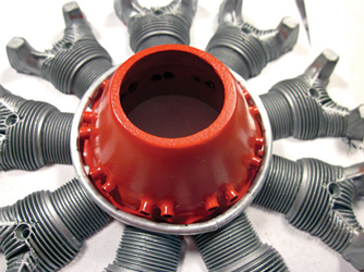
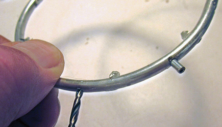
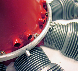
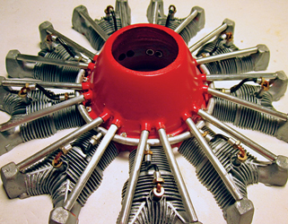
I sprayed the crankcase with Stits PolyTone Madrid Red. The ignition harness ring around the perimeter of the crankcase is more 3/16-inch K&S tubing bent by hand around a bottle that happened to be the correct size.
Step 15.
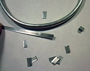
There are too many individual differences among the various engines you might encounter for me to describe every possible detail. On my P&W R-985, the ignition harness ring is mounted to the crankcase by small metal brackets and bolts. Using my photo references I cut a strip of .007 inch lithoplate (aluminum), snipped it into short lengths, and bent each of the pieces in turn into a bracket.
Step 16.
Each simulated ignition ring mounting bracket gets assembled to the ring housing using SLO-ZAP.
Step 17.
Here I am opening up holes to fit more little bits of K&S tubing using the good old Dremel tool.
Step 18.
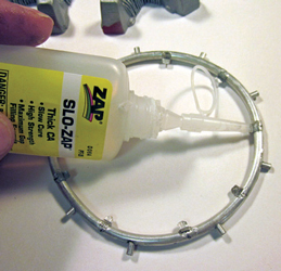
Each of the ignition wires exits the ring through a dedicated tube. On the full scale engine these are welded in place. On this model, each of the ignition lead guide tubes gets inserted into its hole in the ignition ring and ZAP’d into place.
Step 19.
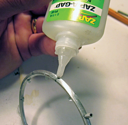
Now, reinforce the bond between each of the simulated mounting points and the ring with a drop of ZAP-A-GAP.
Step 20.
The ignition harness ring is in place, secured by more SLO-ZAP in the back where you can’t see it.
Step 21.
On the full-scale engine those brackets are attached using A-N machine screws which are finished in a gold color. I used some tiny simulated copper rivets I found in a model railroad shop, drilled appropriate holes through each bracket into the crankcase behind it, and ZAP’d each one into place.
Step 22.
Spark plug locations are represented by rings cast into the dummy engine. I used more 5/32-inch K&S tubing cut into appropriate lengths to represent the spark plug housings and drilled out each cylinder to accept them.
Step 23.
Each spark plug body gets set into a drop of ZAP-A-GAP.
Step 24.
This is the spark plug body in place. Note that when this particular dummy engine is mounted inside my cowl, a lot of this detail, including these spark plugs, will be partially obscured, and so I am keeping those assemblies simple.
Step 25.
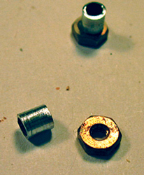
The actual ignition leads are shielded cable attached with threaded housings. I am going to represent those using some brass 2-56 nuts from my junk box and more aluminum tubing. Watch how this goes together.
Step 26.
I used some leftover 14-gauge black insulated wire for ignition leads. Each piece is inserted at one end into the guide tube in the ignition ring and at the other into the right-angle fixture I made from those 2-56 nuts and short sections of copper tubing (more K&S stuff) bent into 90-degree elbows.
Step 27
As I mentioned earlier, am going to mount the assembled dummy engine to the inside of the cowl. To ensure proper clearance from the Cobra motor I first opened up the center of the dummy casting to provide about 1/8-inch clearance all around. To do the actual mounting I have wrapped masking tape around the Cobra motor to a thickness of 1/8-inch.
Step 28.
The dummy engine is held firmly in place over the Cobra motor by masking tape spacer.
Step 29.
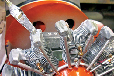
The dummy engine is going to be glued permanently inside the cowl. Here I am applying 30-minute epoxy to each of the previously sanded-down valve covers.
Step 30.
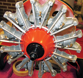
Before adding the epoxy, I doublechecked the fit of the cowl over the engine. Here the cowl is locating in place on the airplane using the standard mounting screws, and held in the correct clearance from the Cobra motor by that masking tape collar. I’m going to let everything cure overnight, then pull the screws, slip the cowl off, and remove the masking tape.
Step 31.
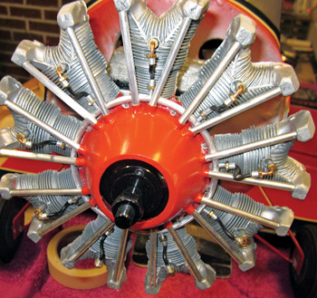
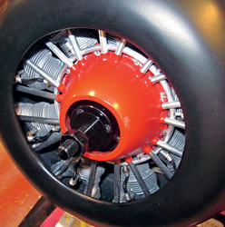
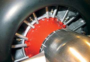
The cowl is secured to the fuselage by four mounting screws, the dummy engine is epoxied inside the cowl, and proper clearance is assured by the masking tape spacer I used during assembly. This is perhaps a nontypical scale radial engine installation in that most of the actual dummy is obscured by the cowl. However, the part you can see grabs your attention, doesn’t it?
THE FINAL WORD
This is where we have run out of page space in this issue of Fly RC, but we’re not done with my presentation. Move over to your computer, go to www.rcmodel.com/2011/09/detailing-a-dummy-scale-engine, and check out the rest of the story.
CONTACTS
STITS stits.com, 817-279-8045
ZAP GLUE zapglue.com, 863-607-6611
